Termpaint - A journey to TUI application development
on 2020-11-28 in tui

For a long time I wanted to write some terminal TUI applications. But for various reason no terminal library really clicked with me.
Coming from classical event loop driven graphical user interface programming, I was mostly looking for something similar just adapted for terminal use. I was first looking for something high level with one of the usual event loops and a nice widget abstraction. But as I said nothing really clicked.
So maybe I had to write that high level library. So next I was looking for some low level library to just do the raw terminal interfacing.
There is of course ncurses, which is the gold standard in support for output to a wide range of terminals. But for input processing it too heavily depends on correct terminfo entries, which sadly in the modern world of frozen in the past enterprise deployments is just not working out too well. Worse these kind of "don't touch anything" of deployments have forced terminals to completely undermine the system with setting $TERM to outright nonsensical values, usually claiming to be xterm, while clearly not being a complete xterm at all. Also a generic event loop was not a common thing back when the standard for curses was written.
Some other libraries did not offer the low level interfaces I wanted -- instead combining the low level parts (a cell matrix and input events) directly with higher level parts I didn't intend to use. Some even used interesting hacks that could never work over ssh for terminal emulator detection. Also I was looking for something with permissive licensing and usable from C or C++ code.
For input handling there is libtermkey which seemed nice, but also was deprecated already. Still this library seemed to have some good ideas and certainly was a good inspiration for how to go about handling terminal input. Specially the idea, that interpreting terminal input with something closely matching a ECMA-48 sequence parser is the way forward instead of just matching against a small list of known terminal inputs.
So I started with experimenting with alternative ways to handle keyboard input. One important part in handling input from terminals is to handle input with graceful degradation when a sequence is not known. While sadly the terminal to application communication is not prefix-free, it follows a certain structure for most of the sequences that allows ignoring unknown sequences. That's something I really wanted to have. It's just ugly to end up with junk characters when trying a key combination that is not supported.
Another important point was that I wanted input processing that nicely fits into a event loop based environment, like it is common in many modern applications. Thus having the input processing mixed with terminal I/O was something that I wanted to avoid.
But following the rabbit hole even deeper now I had to understand how terminals really work.
Documentation of terminals of course varies. The best documented terminal is xterm. It has a full list of almost1 all supported sequences here. It's documentation is terse but complete. Many other terminals applications don't seem to have any up to date documentation of the sequences they support. Documentation of the terminal to application communication isn't very common among terminals either.
So I started looking into the source of various terminals and related standards like ECMA-48. It soon was evident that I needed much more organized notes, or even better some real documentation covering more than just one terminal.
So the rabbit hole now started to bottom out at writing such documentation and learning how the terminals actually work. After reading lots of terminal code (as code speaks more authoritatively than standards from 20 years ago) I ended up with something of an start of understanding how things seem to work. Of course after putting in that amount of work it should be accessible to others so I got that documentation a nice home at https://terminalguide.namepad.de.
Now with a better understanding of how terminals work, I continued experimenting with terminal input processing. Could I avoid using timeouts to disambiguate input? Instead combine input and output together to get the terminal to output further bytes to make deciding easier. That seems to work at least when the terminal connection is reasonably low latency. But that needed to have terminal input and output processing some by one integrated library it seemed.

So that drove me to look more into the output side as well. Output needs to know which terminal implementation is at the other side of the connection a lot more than input2. And looking at $TERM does not really work that well nowadays. So do the terminals differ in responses enough to detect the implementation by finger printing responses? It seems that many of the modern terminals do3. For some even the version is available in that way. Of course finger printing is really not nice (and the code a lot worse) so really we need something better. Maybe we get some feature self reporting by terminals in the future.
So in the end the experiment for terminal input processing morphed into a full low level terminal interface library. Which now is finally available on GitHub.
Termpaint only targets modern VT1xx like terminals. Thus it requires a terminal that supports utf-8 and primarily targets terminals released in the last couple of years. But that is a bit fuzzy with support for xterm versions going back at least to 264 (from 2010, already solid back then and version reporting allows for selectively enabling of features) but other terminals might only cover versions a few years back to some newer terminals like alacritty that are only supported in fairly recent versions.
Termpaint has a core that does not know anything about how bytes go from or to the terminal thus can fit into any event loop or be used with synchronous terminal I/O.
It has a output model with surfaces that are simply two dimensional arrays of cells with styles, colors and chars (with support to wide characters as used with some languages and emoji).
It has terminal fingerprinting instead of using $TERM because too many terminals lie and an application should really work without having to fiddle with "unbreak it" settings. I also try to test it with a lot of different terminals and terminal versions4.
All functions work with the usual SSH setups.
It has text measuring functions heavily inspired by libtickit.
It has an input parsing sub library that is bundled but usable stand alone (could be extracted if there is demand).
Check out termpaint: https://github.com/termpaint/termpaint
Of course, the higher level library is still on my list of things to do. I've got a good start on that code done already, but it will still take some time to be in a state to put it on GitHub.
Nevertheless Termpaint can be useful without having an explicit higher level library as well. Typical terminal interfaces use the rich but constrained nature of text and semi-graphics glyphs with colors and attributes to create interfaces that are quite possible to draw without complicated support libraries. And sometimes doing things by hand can be quite satisfying too.
It's still early, but a friend already came up with a useful application to monitor YouTube channels for new videos and display them. See the screenshot above. It's called yttui and is available at: https://git.schroedingers-bit.net/trilader/yttui
The editor in the screenshot at the top also exists but depends on my unfinished higher level TUI library, so it will be released some time in the future.
xterm has some experimental sequences that are not documented↩
For most part there are not may sequences used for different keys by different terminals. And the most important sequence is backspace which has it's own setting in the terminal interface layer of *nix like kernels that the application can just use. Of course some details still differ and termpaint now uses terminal detection information for input processing as well.↩
But of course many simpler terminals are not really distinguishable by fingerprinting.↩
I've started a collection of flatpaks of terminals to easy testing many versions of terminals living at https://github.com/textshell/flatpak-terminal-zoo↩
Interrupts
on 2016-04-24 in stm32-from-scratch
In this part i am going to add a simple example for an interrupt. And some infrastructure to easily hook up interrupt handlers.
In the first part i added only a minimal vector table needed for getting the code to run. Of course the cpu has more exceptions that it expects to be described in the vector table. So it’s a good idea to fill the table with defined function pointers.
 extern char __stack_end;
 extern void (* const vectors[])() __attribute__ ((section(".vectors"))) = {
                 (void (*)())&__stack_end,
                 Reset_Handler,
+                NMI_Handler,
+                HardFault_Handler,
+                MemManageFault_Handler,
+                BusFault_Handler,
+                UsageFault_Handler,
+                0,
+                0,
+                0,
+                0,
+                SVCall_Handler,
+                DebugMonitor_Handler,
+                0,
+                PendSV_Handler,
+                Systick_Handler,
+                Irq0_Handler,
+                Irq1_Handler,
// ...
Section 2.3 (Exception Model) of the STM Cortex-M3 programming manual describes the exception model and contents of the vector table. The vector tables starts with the initial stack pointer and reset handler as setup in the first post. This is followed by 14 words defined by the arm cortex m system architecture. All that are set to 0 are documented as "reserved" in the reference manuals and i couldn’t find for what they might be reserved.
- NMI
- Non maskable interrupt: can be triggered by software or external interrupt (e.g. clock security system)
- HardFault
- Last resort exception handler
- MemManageFault
- memory access rejected by memory protection unit (MPU)
- BusFault
- bus error while accessing memory
- UsageFault
- e.g. undefined instruction, unaligned access, division by zero (not all enabled by default)
- SVCall
- Call to privileged code via `svc` instruction
- DebugMonitor
- used with certain debugging techniques
- PendSV
- Can be triggered using the “interrupt control and state register” from privileged code
- Systick
- Interrupt for the Systick timer common to all cortex-m
Most of the arm defined exceptions are disabled in the reset state and instead the hard fault is executed. The NMI is always enabled, except when the last NMI execution caused to processor to lockup.
The IrqN_Handler·s are vendor defined peripheral interrupts. The assignment of those to are described in Section 10 (Interrupts and events) of the hardware reference manual.
So what happens when an interrupt is triggered? The process starts with some component detecting that an interrupt should be raised. This can be a part of the hardware via an interrupt line or a part of the software via a bit in a special register.
The interrupt request is signaled to the Nestable Vectored Interrupt Controller (NVIC) which is a part of the arm defined core peripherals. It buffers all interrupt requests in it’s interrupt pending register, even if the interrupt source later is disabled it’s bit in the pending register is not reset. It only uses this pending state if the interrupt is also enabled, if not it just keeps pending but doesn’t have a further effect until enabled. The NVIC tracks which interrupt is activly serviced by the cpu.
Each interrupt is assigned a priority. Most priorities are configurable by software, only Reset, NMI and hard fault have fixed priorities higher than any other interrupt. Among themselves Reset has the highest priority, followed by NMI and hard fault. Interrupts have higher priority if their priority value is a lower number.
The NVIC looks at the interrupt with the highest priority. If the CPUs PRIMASK, FAULTMASK and BASEPRI setting allow execution of the interrupt and if the CPU is serving no interrupt or a interrupt of strictly lesser priority it will initiate processing of the interrupt. In this process if stack alignment is needed (STKALIGN in SCB_CCR set and stack not aligned to 8 bytes) the stack is aligned and bit 9 (reserved) in PSR is set. Next the cpu will push registers R0-R3,R12,LR,PC and PSR to the stack that was active before serving the interrupt and then activate the main stack in case the process stack was active before. In this tutorial everything runs on the main stack.
The cpu will then set LR to a special class of values (EXC_RETURN) used later when returning from the interrupt. Also the currently executed interrupt is stored in the IPSR cpu register. The cpu then resumes execution on the first instruction of the interrupt handler as indicated in the vector table.
This whole procedure means that the interrupt looks to the called handler like a normal C calling convention abiding function call with no arguments from a piece of code running in privileged mode on the main stack. Thus we can use normal C++ functions for interrupt handling. All registers not saved by interrupt entry will be saved by the code generated for the function if the function needs to write to them. As i said before, cortex m is very C friendly.
When the interrupt handler returns it will load the special value from the LR register as new execution address. This will be detected by the cpu (if done via a supported instruction for interrupt return and while processing an interrupt) and the following special handling will be triggered. The lower 5 bits of the LR value encode if it was a nested interrupt and which stack was in use when the interrupt was started. The cpu then switches to the stack that was active before the interrupt and pops of the saved register contents and if needed undoes the stack alignment (controlled by bit 9 of the stacked PSR). For some long running instructions with side effects (LDM and STM) the cpu has special logics to resume partially executed instructions.
In most cases an interrupt handler needs to explicitly acknowledge the cause of the interrupt, because many interrupts are level triggered which means as soon as the handler returns that would be called again if the handler didn’t acknowledge them.
In cortex m cpus there are also a few of mostly software transparent optimisations like that when an interrupt of higher priority arrives while preparing for an interrupt the higher priority interrupt replaces the previous interrupt (so called late arriving optimisation) and that if another interrupt needs to be executed when the current one is finished it doesn’t need to execute a complete unstack/restack cycle (tail-chaining).
Ok, now we know that the cpu architecture does a lot work to allow application code to run like a normal function call even if called as interrupt handler. So a simple default interrupt handler for unexpected interrupts looks like this:
void Default_Handler() {
    while (true) {
        ;
    }
}
This is not really useful because it just catches the cpu in an endless loop. But for simple projects this is a safe state. In other situations an unexpected interrupt might be better served with shuting down hardware and maybe triggering a reset. But let’s work with this simple default handler:
void Default_Handler();

extern "C"
void Default_HandlerWrapper() {
    Default_Handler();
}
#define DEFINE_HANDLER(name) void name ## _Handler(void) __attribute__ ((weak, alias("Default_HandlerWrapper")));
The main idea here is to have all possible exception handlers weakly aliased to the default handler. The linker will pick either the default handler or a strongly defined function defined in a different file as the value to put into the vector table.
First i need a local wrapper for the default handler because the alias attribute needs a symbol defined in the same compilation unit. Then i’m using the preprocessor here to keep repeated code at a minimum and seperate different aspects a bit. The name of the aliased function is contructed from the macro parameter with an appended _Handler.
#define Irq0_Handler  WWDG_Handler
#define Irq1_Handler  PVD_Handler
// ...
#define Irq25_Handler TIM1_UP_Handler
// ...
#define Irq67_Handler USB_FS_Handler
In this file we need to order the exception handlers in the vector array by number. I decided
to use a layer of preprocessor macros to keep the dependance on their concrete use minimal.
So i setup a series of macros that just map the vendor specific mapping of irq number to the
cleartext name. So later it’s easy to ensure that the vector array is correctly build and
it’s easy to check the mapping from irq number to function name because by construction the
correct number is right beside the cleartext name. This needs to be placed before any other
usage to the IrqN_Handler names is made in this file. As the compiler after preprocessing
sees the cleartext names the macros are only needed in the file containing the
DEFINE_HANDLER calls and the vector array.
DEFINE_HANDLER(NMI)
DEFINE_HANDLER(HardFault)
DEFINE_HANDLER(MemManageFault)
DEFINE_HANDLER(BusFault)
DEFINE_HANDLER(UsageFault)
DEFINE_HANDLER(SVCall)
DEFINE_HANDLER(DebugMonitor)
DEFINE_HANDLER(PendSV)
DEFINE_HANDLER(Systick)
DEFINE_HANDLER(Irq0)
DEFINE_HANDLER(Irq1)
// ...
DEFINE_HANDLER(Irq67)
This code setups the alias for every exception. It also uses the macro layer so it’s easy to maintain.
That’s it for the preliminaries and intrastructure. Let’s revisit the blinking code but using a timer interrupt:
void TIM1_UP_Handler() {
    // Clear interrupts
    TIM1->SR = 0;
    GPIOC->ODR ^= 1 << 13;
}
I’ve chosen timer TIM1 for this post. It has a dedicated update interrupt that is invoked when it’s counter is reset. First the code acknowledges all conditions of the timer. In real code this acknowledge should likely be more selective but what needs to be acknowledged is highly application dependent. After that the handler flips the bit corresponding to the LED in the output data register of the gpio block. Keep in mind that this reads the register, modifies it and replaces the register content with the new value. Thus this is not an atomic operation.
Next the timer needs to be setup:
void initTimer() {
    RCC->APB2ENR |= RCC_APB2ENR_TIM1EN;

    RCC->APB2RSTR |= RCC_APB2RSTR_TIM1RST;
    RCC->APB2RSTR &= ~RCC_APB2RSTR_TIM1RST;

    TIM1->DIER = TIM_DIER_UIE;
    TIM1->CNT = 1;
    TIM1->ARR = 732 / 2;
    TIM1->PSC = 0xffff;
    TIM1->CR1 = TIM_CR1_CEN;

    // Clear interrupts
    TIM1->SR = 0;

    NVIC_EnableIRQ(TIM1_UP_IRQn);
    NVIC_SetPriority(TIM1_UP_IRQn, 15);
}
This is fairly straight forward. The first three lines enabled and reset the timer.
TIM_DIER_UIE enables the interrupt generation for update events. Then the initial
counter (CNT), the reload value (ARR) and the prescaler (PSC) as set so that the timer
will trigger approximately twice per second (48MHz / (0xffff+1) / 732 / 2 = 0.50028… Hz).
Timer TIM1 runs in this case with full APB2 frequency (see clocktree, APB2 divider is set
to 1x so the additional divider for TIM1 is disabled).
After the timer is setup, it get’s enabled (CR1_CEN) and all pending interrupts acknowledged. Then the interrupt is enabled in the NVIC and it’s priority is set to the lowest value. I’m using function from the arm CMSIS headers here, because they for once do the straight forward thing.
We just need to use the code now:
        initTimer();
        while (1) {
            ;
        }
After starting the timer all that’s left is loop waiting for interrupts.
When you try to run this programm please be sure to use a hardware reset without bootloader.
Starting using stm32flash -g0 will possibly not work at this point.
I encountered a very strange effect when first trying to enable interrupts on this system.
In the end the explaination was that stm32flash -g0 has two possible modes of operation.
If the pin BOOT0 still is pulled high to select the bootloader it will just jump to the
reset handler of the code in the flash, but the remapping of the low address space still is
in place. On the other hand if BOOT0 is no longer pulled high the remapping will be as
after a clean reset. I can only guess that that is what happens. If possible it triggers a
hardware reset, otherwise is does a partial emulation. In case of the emulation the end
result is that the exception vector of the bootloader is still in place and interrupts fail
horribly. So beware that the environment for code started from the bootloader can subtly
differ from a real reset.
In this case there is an easy fix:
    extern uint32_t vectors;

    SCB->VTOR = (uint32_t)&vectors;
It explicitly sets the NVIC to use the vectors from their address in flash instead of relying on the remapping. With this code added interrupts also work reliable when starting using the bootloader.
Another potential reliablity problem with the current code is that the gpio is accessed with a non atomic read-modify-store cycle. If this cycle is interrupted by an interrupt with higher priority that also modifies this register some modifications will be lost.
One solution would be to block interrupts using PRIMASK before the modification and to
reenable them after the modification is complete. Another possibility is to use the
bitbanding engine available in cortex m3 and higher. It abstracts atomic bit set and clear
into a memory mapped peripherial. For supported ranges of SRAM and device registers for
every bit there is a 32bit word where the least significant bit is mapped to the bit in the
original memory region. This is still implemented as a read-modify-write cycle so it
should not be used on registers where writing the current value would have any
side-effects (e.g. write 1 to clear bits, etc). But this is atomic with regard to cpu
and even DMA accesses from the system. So it‘s a nice way to implement atomic bit
operations. It does not support toggeling a bit atomically. So using it to toggle a
bit uses 2 reads and one write and is not atomic with regard to this one bit. So if any
other code can also change the value of the bit some other protection will be needed.
template <unsigned reg, unsigned bit>
constexpr __IO uint32_t& bit_band_alias_impl() {
    static_assert((0x40000000 <= reg && reg <= 0x400FFFFF)
                  || (0x20000000 <= reg && reg <= 0x200FFFFF), "reg outside bitbandable area");
    static_assert(bit <= 31, "bit must be <= 31");

    return reg >= 0x40000000 ? (*((uint32_t*)(0x42000000 + (reg - 0x40000000) * 32 + bit * 4)))
                             : (*((uint32_t*)(0x22000000 + (reg - 0x20000000) * 32 + bit * 4)));
}
#define bit_band_alias(reg, bit) bit_band_alias_impl<(unsigned)&(reg), bit>()
This combination of a macro and an constexpr template function allows safe compile time
checked and calculated access via bit banding. The two static_assert ensure that no out
of range input can accidentially slip through. Templates doen’t allow pointers to calculated
memory locations as non type parameters. So a macro is needed to hide the typecast.
Usage is:
bit_band_alias(GPIOC->ODR, 13) ^= 1;
One last improvement is to save power in the idle loop. If the code just waits for an interrupt the wfi (wait for interrupt) instruction can be used to enter sleep mode while waiting for the interrupt:
         while (1) {
-            ;
+            __WFI();
         }
In my setup this saves around 20mA. So it’s an easy way to reduce power consumtion without much work.
Code as always available as git commits.
STM32 PLL and Crystal Oscillator
on 2016-04-11 in stm32-from-scratch
After some more toolchain oriented posts in this series, let’s get back to the actual micro controller. Since the first part of this series the sample code is running using the default 8MHz internal clock. In this part I'm going to enable the external oscillator and use the PLL (phase locked loop) to scale it’s frequency up to run the microcontroller at a faster pace (and more energy consumption, of course).
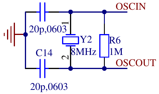
The board i’m using has an 8MHz quarz crystal and the needed passives connected to he external oscillator pins of the microcontroller.
    // enable high speed external oscillator
    RCC->CR = (RCC->CR & ~RCC_CR_HSEBYP) | RCC_CR_HSEON;
    while (!(RCC->CR & RCC_CR_HSERDY)) {
        ;
    }
The first step is to enable the oscillator circuit by setting RCC_CR_HSEON. RCC_CR_HSEBYP would
enable to use an external clock without the oscillator circuit so we ensure that it is disabled.
The while loop waits until the oscillator circuit has a stable frequency by waiting for
RCC_CR_HSERDY to be asserted by the hardware. This HSE clock is now ready to be used by other
parts in the clock tree.
To run the microcontroller at a higher frequency the the next part is the PLL (phase locked loop). I use it to multiply the output frequency of the HSE to get a 48MHz clock to run the microcontroller.
    // init pll
    int pllmul = 6;
    RCC->CFGR = (pllmul-2) << 18 | RCC_CFGR_PLLSRC | RCC_CFGR_PPRE1_DIV2;
    RCC->CR |= RCC_CR_PLLON;

    while (!(RCC->CR & RCC_CR_PLLRDY)) {
        ;
    }
The PLL multiplier is encoded with an offset of 2, so I prefer to put the multiplier as number
into a variable and apply the offset seperately while constructing the register value. The PLL
can use either the internal 8MHz oder the HSE clock as input RCC_CFGR_PLLSRC selects HSE.
This will output a 48 (8 * 6) MHz clock. The system clock is used to derive various other clocks.
Of of these clocks is the APB1 clock. This clock may not exceed 36 MHz. To prepare for using the
output of the PLL as system clock, the divider for APB1 needs to be set to 2 (RCC_CFGR_PPRE1_DIV2)
so i will only get a safe 24MHz. After setting RCC->CFGR the code enabled the PLL (RCC_CR_PLLON)
and again waits for it to stabilize by polling for RCC_CR_PLLRDY.
The next code is not strictly needed. But when using the serial port to debug it‘s useful to make sure that all data is send before changing the system clock to avoid garbled output. If the serial port was not in use before the frequency change it shouldn‘t delay startup by more than a few cycles.
    if (RCC->APB2ENR & RCC_APB2ENR_USART1EN) {
        // if usart1 is clocked wait to drain possible debugging infos.
        while ((USART1->SR & (USART_SR_TXE | USART_SR_TC)) != (USART_SR_TXE | USART_SR_TC)) {
            ;
        }
    }
Finally it’s time to actually switch to the clock generated by the PLL.
    // switch sysclock to pll
    RCC->CFGR |= RCC_CFGR_SW_PLL;

    // wait for ack
    while ((RCC->CFGR & RCC_CFGR_SWS) != RCC_CFGR_SWS_PLL) {
        ;
    }
And of course wait for the switch to be acknowledged by the hardware. And that’s it. The microcontroller is now switched to 48 MHz. Of course the serial code and the delay while blinking have the frequency hardcoded. So we need to change those to use 48 MHz instead of 8 MHz for calculations.
Code as always available as git commits.
1. STM32 from scratch, the bare minimum
2. STM32 from scratch, the hardware
3. STM32 from scratch, serial
4. Makefile for embedded projects
5. Enabling C/C++ features
6. Heap, malloc and new
8. Interrupts
Heap, malloc and new
on 2016-04-10 in stm32-from-scratch
Sometimes dynamic memory allocation is needed. While often allocating memory statically leads to a more robust system, it’s not always possible within the contraints of the hardware.
In microcontrollers with a simple memory map of only one RAM area, the heap is just the part of the RAM that is not used by anything else in the linker script. So we can just add this after the last section that is put into RAM (.bss in this case):
+    __heap_start = .;
+    __heap_end = ORIGIN(RAM) + LENGTH(RAM);
+
+    /* Don't place any sections that are actually used on target system after the heap without adjusting _heap_end above */
In a sense that‘s all that needs to interact closely with the toolchain. Using __head_start and
__heap_end you can implement you own allocator. If you call your allocation function malloc
gcc does some optimizations based on builtin assumsations about functions from the C standard, so it
might optimize out calls when you don‘t expect.
As i don‘t usually use dynamic memory allocation i tend to resort to use the malloc implementation from newlib in it’s nano configuration that is shipped with the toolchain.
To enable the nano configuration of the libc we need to pass -specs=nano.specs in the final link
command. Newlib expects a traditional unix like sbrk function for heap size management.
/* needed for malloc in newlib */

extern "C" void* _sbrk(int increment);
void* __attribute__((weak)) _sbrk (int increment) {
    extern char __heap_start;
    extern char __heap_end;

    static void* __heap_top = &__heap_start;

    void *new_heap_top;
    if (__builtin_add_overflow((intptr_t)__heap_top, increment, (intptr_t*)&new_heap_top)) {
        return (void*)-1;
    }
    if (!(&__heap_start <= new_heap_top && new_heap_top <= &__heap_end)) {
        return (void*)-1;
    }

    void* old_top = __heap_top;
    __heap_top = new_heap_top;

    return old_top;
}
_sbrk is a fairly simple wrapper around a static variable that keeps track of the part of the
heap already handed out to the malloc implementation, while checking that it stays inside of the
heap. It is careful about integer overflows and uses the compiler intrinsic __builtin_add_overflow
(needs a recent gcc to work).
With this bit of support code the newlib malloc should be usable. Or an other simple malloc
implementation that uses sbrk.
With an working malloc implementation the new operator also works. Because we‘re using c++ without
exceptions remember that it spells as new(std::nothrow) and needs #include <new>
The support code is included here
1. STM32 from scratch, the bare minimum
2. STM32 from scratch, the hardware
3. STM32 from scratch, serial
4. Makefile for embedded projects
5. Enabling C/C++ features
7. STM32 PLL and Crystal Oscillator
8. Interrupts
Enabling C/C++ features
on 2016-03-16 in stm32-from-scratch
Now that i have a really minimal program with possibly of debug output it's time to expand the capabilities a bit. While this setup barely works for blinking an LED most C++ and even most C features are not working yet.
Section garbage collection
The first step actually doesn't add a real feature. It just reduces the code memory usage. By default g++ produces object files that have all code in one section so the linker can either add all of it to the final linked file or nothing. And the linker reasonably includes all code from every object file. That’s nice and predictable. It’s also wasteful, because code get’s included that is not actually used.
There are two main reasons for this unused code. The first one is the there might be functions in the code that are not actually called. That can of course happen easily if some files are more of a library nature or some calls are conditionally compiled (depending on debug options for example).
The second reason is that g++ often inlines code, but without beeing explicitly told that it will not be used also emits an non inline version. For example in the current code the functions for using the serial port are likely inlined. But they are not declared static so g++ must prepare an object file that also has duplicate code. One fix is to always add static for these functions. But i think it’s better to let the computer figure that out automatically. Even though marking file local functions with static is a good idea, often we don't know if there is an outside user. Fundamentally static is about keeping private functions private and the global namespace clean, not about encoding cross file usage of functions in source. In case of the simple serial code serial_writebyte_wait is currently only used by serial_writestr, but it’s reasonable to export. Tracking if there currently is an external user or not and adding a static wouldn't make for cleaner code. But just for busy work and unneeded coupeling.
So i’m going to allow the linker to remove unneeded code. But how would the linker know what code is needed in the first place? If the linker has some code (or rather section) that it needs to include in the linked output it will fullfill every symbol referenced in that section either from other object files included directly into the build or from included static libraries. But there needs to be an initial section to start this from. The current linker script doesn’t have anything that would act like an anchor for the linker to start from. Using KEEP in the linker script we can declare sections that always need to be included even if the linker doesn't see any references to it from other already included sections. In this case .vectors always needs to be included because it contains the pointers the cpu uses when starting up:
     .vectors : {
-        *(.vectors)
+        KEEP(*(.vectors))
     } > FLASH
This will make sure the linker has something as root for determining what need to be included. Of course we still need to tell the linker to only include needed sections.
LDFLAGS += -Wl,--gc-sections
This enables the section garbage collection. So far this would remove completly unused files (actually it considers code and data separately, but i don't have data sections yet at this point). To make this effective at function level g++ needs to generate each independent function into it's own section. And while we are at it for data too:
CFLAGS += -ffunction-sections -fdata-sections
CXXFLAGS += -ffunction-sections -fdata-sections
These optionas are not always good. There are some tricks with weak symbols and bigger sections to ensure that when a feature of a library is used the the needed infrastructure is only then brought in. But that‘s more what you need to worry about when writing the standard c library.
The result of these flags is for this sample program a reduction of code size from 312 bytes down to 172 bytes (about 45% of the previous size). Of course this is because g++ did a lot of inlining in this case and everything is just in one file. In real applications size reduction is not expected to be this large.
Explicitly placing read only data
The example code contains a string that is printed to the serial port. g++ emits this to a .rodata section that is not placed explicitly by the linker script. While this might be convinient, i like my memory layout to be easier to predict and thus decided to place everything explicitly. Thus after the .text output section in the linker script:
    .rodata : {
        *(.rodata*)
    } > FLASH
This just gathers all sections beginning with .rodata into flash at this point in the linked image.
Guarding against automatic placement of unknown elf sections
To take this a bit further i like to make my build fail if it produces sections i did not explicitly map in the linker script. Often special sections need some kind of special handling. Thus i prefer the “fail early, fail hard” approch. If the build can detect a potential problem, i want it to fail so i can avoid needing to debug it later in a running micro controller.
ld has a promising sounding option --orphan-handling=error for that. Orphans beeing unmapped sections in this context. Sadly there are quite many sections even in this small sample program that are not explicitly mapped. So let’s start mapping a few of them:
    /* debug information, intentionally only support for modern dwarf */

    .debug_info 0 : { *(.debug_info*) }
    .debug_abbrev 0 : { *(.debug_abbrev*) }
    .debug_loc 0 : { *(.debug_loc*) }
    .debug_aranges 0 : { *(.debug_aranges*) }
    .debug_ranges 0 : { *(.debug_ranges*) }
    .debug_macro 0 : { *(.debug_macro*) }
    .debug_line 0 : { *(.debug_line*) }
    .debug_str 0 : { *(.debug_str*) }
    .debug_frame 0 : { *(.debug_frame*) }
The makefile creates debug information. This just passes these though to the output file. The sections’ attributes in the object files make sure that they don’t end up in the actual flash image.
    /DISCARD/ : {
        *(.note.GNU-stack)
        *(.gnu_debuglink)
        *(.gnu.lto_*)
        *(.comment)
        *(.ARM.attributes)
    }
These section can just be discarded for various reasons.
- .note.GNU-stack: Properties about executable stacks.
- .gnu_debuglink: Reference to Debugging Information in Separate Files
- .gnu.lto_*: Link time optimization itermediate code
- .comment: Version of the compiler used to generate object files
- .ARM.attributes: built attributes
The linker implicitly creates some section while processing the object files. These have to be empty for what is supported by this linker script and the system initialization. So the next step is to match them all into a section and bail out if that section contains anything:
    /* complain about contents in any sections we don't support or know about that linker or assembler generate */
    .unmatched : {
        KEEP("linker stubs"(*)) /* .glue_7 .glue_7t .vfp11_veneer .v4_bx */
        KEEP(*(.iplt))
        KEEP(*(.rel.iplt))
        KEEP(*(.igot.plt))
    } > FLASH
    ASSERT(SIZEOF(.unmatched) == 0, "allocated sections not matched. Search in linker map for .unmatched and add non empty sections explicitly in this file")
These are mostly for interworking between thumb and non thumb machine code(which can’t happen on cortex m because it only supports thumb) and advanced linker tricks (STT_GNU_IFUNC).
Now that we have discarded or matched we can finally add -Wl,--orphan-handling=error to the makefile. Sadly this is quite a big part in the linker script. But i believe it's worth knowing if something is emitted unexpectedly.
Move stack definition into linker script
The minimal example hard coded the starting value for the stack pointer in the code. But going forward the layout of data in the sram should be managed by the linker. So let’s start by moving the placement of the stack into the linker script.
First we need to define the memory for the sram:
 MEMORY {
     FLASH : ORIGIN = 0x08000000, LENGTH = 64K
+    RAM :   ORIGIN = 0x20000000, LENGTH = 20K
 }
This adds a new memory called RAM with the given address and length.
+__stack_size = 0x400;
For convinence define a constant for the wanted stack size. This is likely more than a simple project needs. But when experimenting it‘s nice to be on the safe side for now.
    .stack : {
        __stack_start = .;
        . = . + __stack_size;
        __stack_end = .;
    } > RAM
This adds a section called .stack and sets its size by incrementing the . current address variable. Also it defines symbols __stack_start and __stack_end with which refer to the start and end of the section. The end is to be used in the c++ code for initializing the initial stack pointer. The start is not needed currently, but for other sections both are needed so i added it for .stack too.
-
+extern char __stack_end;
 extern void (* const vectors[])() __attribute__ ((section(".vectors"))) = {
-                (void (*)())0x20000400,
+                (void (*)())&__stack_end,
                 mainFn,
 };
This removes the hardcoded value for the stack start. Getting the address of a symbol created in the linker script is a bit convoluted. We need to define an external variable (type doesn’t matter really) and take it’s address.
Prepare for more test code
- Add test-language-features.cpp with an empty
run_testsfunction. - Add test-language-features.h
- Add serial.h with declaration of
serial_writebyte_waitandserial_writestr - call the
run_testsfunction just before the loop inmainFn()
Adding support for variables without initialization
The goal is to make this code run and not output an '!' even when the cpu is only soft reset. C and C++ standards guarantee that not explicitly initialized global variables are initialized to what effectivly is all bits zeroed on most architectures (including arm)
char test_global;

void global_variable() {
    if (test_global != 0) {
        serial_writebyte_wait('!');
    }
    test_global = 'a';
    serial_writebyte_wait(test_global);
    test_global = 'b';
    serial_writebyte_wait(test_global);
}
So for this to compile we need a linker section to map .bss sections where gcc will place the variable into our resulting linked program. This will not actually create anything in the rom image. But the linker can now assign addresses to the variable and resolve the relocations for the variable in the code in the object file.
    .bss : {
        __bss_start = . ;
        *(.bss*)
        __bss_end = . ;
    } > RAM
This again adds symbols for start and end. This time both are needed to fill the memory with the required zero bit pattern. This is done with a small c++ function:
void init_sram_sections() {

    extern uint32_t __bss_start, __bss_end;

    for (uint32_t* dst = &__bss_start; dst< &__bss_end; dst++) {
        *dst = 0;
    }
}
Again to get pointers from the symbols there are extern variables. I used uint32_t here, because that gives pointers that are useful for the initialization loop. Additionally i added a call to this function at the start of mainFn.
Common sections
Gcc per default allows multiple definitions of variables in C mode(contrary to the C standard). To do that it uses common sections that are apart from build in weak semantics similar to .bss. To test and support that we need a C test file and a little addition to the linker script.
     .bss : {
         __bss_start = . ;
         *(.bss*)
+        *(COMMON)
         __bss_end = . ;
     } > RAM
And in a new file test-language-features-c.c
#include "serial.h"

char test_common;


void run_tests_c(void) {
    if (test_common != 0) {
        serial_writebyte_wait('!');
    }
}
While with the linker script addition it works, i prefer to disable that extension in the makefile. Because we should be writing correct code anyways:
CFLAGS += -fno-common
Initialized globals
Next up is support for initialized globals:
+char test_init = 'c';
+
 void global_variable() {
     if (test_global != 0) {
         serial_writebyte_wait('!');
     }
     test_global = 'a';
     serial_writebyte_wait(test_global);
     test_global = 'b';
     serial_writebyte_wait(test_global);
+
+    serial_writebyte_wait(test_init);
+    test_init = 'd';
+    serial_writebyte_wait(test_init);
 }
For this to work the memory location where test_init is located at runtime needs to be initialized before starting the main part of the program. The program when the cpu is reset is only an flash image. So we need the initialization values somewhere in flash. And they need to be copied to ram early by the reset vector.
For this reason the linker allows us to have two locations for a section. One for an initialization image in flash that is actually included in the flash image and one for use at run time that is located on a different address that is in ram.
    .data : {
        *(.data*)
        . = ALIGN(4);
    } > RAM AT>FLASH

    __data_start_flash = LOADADDR(.data);
    __data_start_ram = ADDR(.data);
    __data_size = SIZEOF(.data);
Here we have LOADADDR that returns the address of the initialization image and ADDR that return the run time location. Together with the size of the data section that’s enough to extend init_sram_sections to copy the initialization image into the correct ram location:
    extern uint32_t __data_start_flash, __data_start_ram, __data_size;

    uint32_t *src = &__data_start_flash;
    uint32_t *dst = &__data_start_ram;
    uint32_t *dend = dst + ((uint32_t)&__data_size);

    while (dst < dend) {
        *dst++ = *src++;
    }
Ok that’s the basics. Using only the language features enabled at this we could build quite a bit without needing to resort to strange workarounds.
Constructors
But there are a few more things that are easy to enable and useful. Constructors is certainly one. Having things run implicitly in the startup might be not be a good idea if we are not careful. But maybe it is if we are. One of the classic problems is that ordering is not well defined for C++ constructors. But that's just standard C++. The gnu toolchain supports constructors with explicit priorities.
Depending on your preferences this could be a nice feature to decouple various parts of code or a pure horror show. Let’s assume we don’t abuse it and go on to add support.
The syntax that is independent of classes (available in C and C++) is:
__attribute__((constructor (202)))
static void constructor2() {
        serial_writebyte_wait('2');
}

static void constructor1() __attribute__((constructor (200)));
static void constructor1() {
        serial_writebyte_wait('0');
}
Both synaxes work. The priority can be from 0 to 65535. The documentation claims that 0 to 100 are reserved. So let’s avoid those.
The way this works is simple. Pointers to the constructor functions are generated into .init_array.XXXXX sections, where XXXXX is the zero padded priority. We just need to arrange for them to be called on startup in the right order. Fortunatly the other special support for this in the toolchain is that the linker can sort these sections by numeric order using SORT_BY_INIT_PRIORITY so getting a list in the right order is easy in the linker script:
    .init_array : {
        __init_array_start = .;
        KEEP(*(SORT_BY_INIT_PRIORITY(.init_array.*)))
        __init_array_end = .;
    } > FLASH

    /* .fini_array ommited because when would we run destructors? */
As usual there’s a start and end symbol to allow for iteration in the startup code. The same infrastructure is available for destructors instead of constructors. But as the comment in the linker script says there is usually no clear time to run those on embedded microcontrollers. So i left out support for this.
The code to run the constructors is similar to the code for memory initialization. It just iterates over function pointers and calls them this time:
void run_init_data() {
    typedef void (*init_fun)(void);
    extern init_fun __init_array_start, __init_array_end;

    init_fun *ptr = &__init_array_start;
    while (ptr < &__init_array_end) {
        (*ptr)();
        ++ptr;
    }
}
Another way to use this for classes is the init_order attribute.
Some_Class B __attribute__ ((init_priority (543)));
This works exactly like the examples above from the linker and runtime support perspective. But there’s one special case. Constructors of global variables without priority are generated into the section .init_array (without a dot and a priority). To support this case we need a tiny addition to the linker script:
     .init_array : {
         __init_array_start = .;
         KEEP(*(SORT_BY_INIT_PRIORITY(.init_array.*)))
+        KEEP(*(.init_array*))
         __init_array_end = .;
     } > FLASH
The default linker script of the toolchain places constructors without explicit priority as after all with priority which seems sensible, so i kept that ordering.
Ignoring global destructors
Now that we have support for constructors in globals, what about destructors?
As i wrote earlier global destructors are not really useful in most embedded environments. But they are often when using the same class in automatic or dynamically allocated storage. So i decided that i want to ignore them in global context. While there is a .fini_array g++ doesn't use it for destructors. Instead it uses an arm abi definied variant of atexit that is called from the function in the .init_array* section that does the construction. Likely to be sure that the destructor ordering is always the exact reverse of the construtors. And because the ARM C++ ABI specifies this.
While the micro variante of newlib shipped with the toolchain i use has an implementation of __aeabi_atexit to just ignore the calls can be done easier with an empty function. And it uses less code space. For reasons that are only relevant in environments using shared libraries the __aeabi_atexit function has an additional argument that is passed the contents of the symbol __dso_handle which is used to identify the shared object from where the call was made. As the value if the symbol doesn’t matter we can just define that symbol to 0 in the linker script.
__dso_handle = 0;
and then implement an empty __aeabi_atexit:
// No atexit, no destructors

// actual signature is bool __aeabi_atexit(void* object, void (*destroyer)(void*), void* dso_handle)
extern "C" void __aeabi_atexit() {
}
I used the wrong signature here to save a few bytes because the return is ignored anyway and all parameters fit into registers. This of course is a questional gain for relying on such low level details. But i sometimes i just can’t help myself from doing stupid micro optimisations.
Statics in functions
In C++ we can have static variables in functions that are initialized by code run when the function is executed for the first time. Of course as we expect from a good general purpose toolchain this is done in a thread safe manner. Nice. Well that of course needs runtime support and is totally unneeded in a single threaded design with interrupts. Well if a function that uses such a static is used from an interrupt this would be needed, and it would need to disable the interrupt. If you want to use statics in interrupts you have to reimplement __cxa_guard_acquire and __cxa_guard_release anyway. For single threaded use without usage in interrupts there is a easier way:
CXXFLAGS += -fno-threadsafe-statics
That is just to disable thread safeness and being careful in using this feature. But when implementing code that needs to be run from an interrupt being careful is always needed anyway.
For full code see here
1. STM32 from scratch, the bare minimum
2. STM32 from scratch, the hardware
3. STM32 from scratch, serial
4. Makefile for embedded projects
6. Heap, malloc and new
7. STM32 PLL and Crystal Oscillator
8. Interrupts
Makefile for embedded projects
on 2016-02-28 in stm32-from-scratch
Remembering or copying the build commands isn't going to be a usable way to build the example project in this series. So we need a makefile to automate this task. While make isn't the nicest tool it's basic working is well understood and it's still the defacto standard.
This will not be a tutorial for make. But i try to explain at least some basic points. First lets start with a makefile that just replicates what we previously did manually. Adding support for C and assembler files for completeness.
C_SRC =

CXX_SRC = main.cpp

ASM_SRC =

DEFINES =

INCLUDEDIRS = -iquote . -I common/stm_include -I common/cmsis_include

PROJECT = minblink

LD_SCRIPT = linkerscript.ld
The first part is the section that defines the variables which contain the source files to process and similar project specific configuration. It starts with the variables for all the source files: C_SRC for plain c files, CXX_SRC for c++ files and ASM_SRC for assembler source files(using .S as file extension).
Alternativly you can move up the OBJ_FILES line and add the resulting .o files there directly without the code to replace the source extensions by .o. In that case you can remove the *_SRC lines. But as this is setup to output everything in out/ you either need to add that explicitly or keep the transformation with addprefix.
After that are project global settings. PROJECT defines the name of the output files. INCLUDEDIRS specifies the gcc/g++ parameters that relate to the include file directories. DEFINES allows specifing macros that should be defined using the usual -DVAR=VALUE syntax. LD_SCRIPT specifies the name of the linker script to use.
TARGET = arm-none-eabi-

OUT=out

CC = $(TARGET)gcc
CXX = $(TARGET)g++
AS = $(TARGET)gcc -x assembler-with-cpp
OBJCOPY = $(TARGET)objcopy
This section defines the output path and shortcut variables for all used toolchain components.
CPUFLAGS = -mcpu=cortex-m3 -mthumb
COMMONFLAGS = $(CPUFLAGS) -MD -MP -MF $(@:.o=.d) $(DEFINES)

CFLAGS = $(COMMONFLAGS) -O2 \
         -std=gnu99 $(INCLUDEDIRS)

CXXFLAGS = $(COMMONFLAGS) -O2 \
         -fno-rtti -fno-exceptions \
         -std=gnu++14 $(INCLUDEDIRS)

ASFLAGS = $(COMMONFLAGS) $(INCLUDEDIRS)

LDFLAGS = $(CPUFLAGS) -T$(LD_SCRIPT) -nostartfiles
-mcpu=cortex-m3 -mthumb -O2 -fno-rtti -fno-exceptions --std=c++14 are the g++ commandline options from the first part. The linker options are the same too.
New is -MD -MP -MF $(@:.o=.d). It instructs gcc to output a file with all dependencies of the currently compiled source in a format that is directly includable in a makefile. This is needed for automatically rebuilding the affected object files when a included header file is changed.
OBJ_FILES = $(addprefix $(OUT)/, $(notdir $(ASM_SRC:.S=.o)))  \
            $(addprefix $(OUT)/, $(notdir $(C_SRC:.c=.o)))    \
            $(addprefix $(OUT)/, $(notdir $(CXX_SRC:.cpp=.o)))
DEPS = $(OBJ_FILES:.o=.d)
Here all source files from the variables defined at the beginning are gathered and transformed into the object file names that will generated for them. These are used as dependencies for linking. Also for make to automate rebuilding objects when included files change make needs files with dependency information. So DEPS is a list of all these dependency files.
# unconditionally ensure output directory
$(shell test -d $(OUT) || mkdir $(OUT))
It’s needed later. So make sure it exists.
all: $(OUT)/$(PROJECT).bin

clean:
    rm -f $(OUT)/*
Define the default target all that just depends on the output of the objdump below. And also define a clean target that just removes all files from out/.
$(OUT)/%.o: %.c Makefile
    @echo CC $<
    @$(CC) -c $(CFLAGS) $< -o $@

$(OUT)/%.o: %.cpp Makefile
    @echo CXX $<
    @$(CXX) -c $(CXXFLAGS) $< -o $@

$(OUT)/%.o: %.S Makefile
    $(AS) -c $(ASFLAGS) $< -o $@
Rules for to transform all supported kinds of source to object files.
$(OUT)/$(PROJECT).elf: $(OBJ_FILES) Makefile $(LD_SCRIPT)
    $(CXX) $(LDFLAGS) $(OBJ_FILES) -o $@

$(OUT)/$(PROJECT).bin: $(OUT)/$(PROJECT).elf Makefile
    $(OBJCOPY) -O binary $< $@
These are the linking and objcopy step for the very first post in this series.
-include $(DEPS)
It’s traditional to add the include for the dependency files at the end.
Now i like to add more features to help understanding my code and to avoid possible problems.
@@ -23,6 +24,6 @@
 OBJCOPY = $(TARGET)objcopy

 CPUFLAGS = -mcpu=cortex-m3 -mthumb
-COMMONFLAGS = $(CPUFLAGS) -MD -MP -MF $(@:.o=.d) $(DEFINES)
+COMMONFLAGS = $(CPUFLAGS) -g -ggdb3 -Wa,-amhlsd=$(@:.o=.lst)  -MD -MP -MF $(@:.o=.d) $(DEFINES)

 CFLAGS = $(COMMONFLAGS) -O2 \
Generation of debug information (-g -ggdb3) is always a good idea. Even without an debug cable for the used hardware it allows running tools like pa-hole that use debug information for further analysis.
The other part (-Wa,-amhlsd=$(@:.o=.lst)) generates a assembler listing files with annotations for every source file. I tend to look into these quite a bit when working on low-level code. While the compiler is free to produce different code, it helps me quite a bit with understanding where i might have parts in my code that are not supposed to be that way. For example it’s quite easy to constrain the compiler from doing useful and safe optimisations, seeing the assembler often leads to a easy fix back in the C++ code.
@@ -26,11 +26,13 @@ CPUFLAGS = -mcpu=cortex-m3 -mthumb
 COMMONFLAGS = $(CPUFLAGS) -MD -MP -MF $(@:.o=.d) $(DEFINES)

 CFLAGS = $(COMMONFLAGS) -O2 \
-         -std=gnu99 $(INCLUDEDIRS)
+         -Wall -Werror=strict-prototypes -Wextra -Werror=return-type \
+         -std=gnu99 -fstack-usage -fverbose-asm $(INCLUDEDIRS)

 CXXFLAGS = $(COMMONFLAGS) -O2 \
+         -Wall -Wextra  -Werror=return-type \
          -fno-rtti -fno-exceptions \
-         -std=gnu++14 $(INCLUDEDIRS)
+         -std=gnu++14 -fstack-usage -fverbose-asm $(INCLUDEDIRS)

 ASFLAGS = $(COMMONFLAGS) $(INCLUDEDIRS)
Also a good idea is to enable warnings and even promote some warnings to errors.
-Werror=strict-prototypes(C only): Yes, prototypes without argument specifications should never happen.-Werror=return-type: Not returning a value from a function declared to have one is bug, not just a warning.-Wall -Wextra: enable useful warnings and errors.-fstack-usage: Let the compiler calculate stack usage for every function.-fverbose-asm: Output more information in the assembler listings.
-LDFLAGS = $(CPUFLAGS) -T$(LD_SCRIPT) -nostartfiles
+LDFLAGS = $(CPUFLAGS) -T$(LD_SCRIPT) -nostartfiles -g \
+          -Wl,-Map=$(OUT)/$(PROJECT).map,--cref -Wl,--print-memory-usage -Wl,--warn-common
-Wl,-Map=$(OUT)/$(PROJECT).map,--cref: instruct the linker to generate a Mapfile with cross reference table.-Wl,--print-memory-usage: Often there is a need to keep an eye on the size of the program to still fit into the hardware’s limits. This prints a summary of the used space as assigned by the linker. (At the time of writing this needed a fairly recent version of binutils, if you have trouble you might need to remove it)-Wl,--warn-common: Warn about sloppy usage of "extern".
OBJDUMP = $(TARGET)objdump
-all: $(OUT)/$(PROJECT).bin
+all: $(OUT)/$(PROJECT).bin $(OUT)/$(PROJECT).lss $(OUT)/$(PROJECT).dmp
$(OUT)/$(PROJECT).lss: $(OUT)/$(PROJECT).elf Makefile
    $(OBJDUMP) -Slw $< > $@

$(OUT)/$(PROJECT).dmp: $(OUT)/$(PROJECT).elf
    $(OBJDUMP) -x --syms $< > $@
Generates some additional information that can help when trying to find out how much space is used by different parts of the program (.lss and .map) and what is actually included in the final linked program.
For full code see here
1. STM32 from scratch, the bare minimum
2. STM32 from scratch, the hardware
3. STM32 from scratch, serial
5. Enabling C/C++ features
6. Heap, malloc and new
7. STM32 PLL and Crystal Oscillator
8. Interrupts
STM32 from scratch, serial
on 2016-02-23 in stm32-from-scratch
In the first part of this series i detailed how to blink an LED. That’s nice and usually the first thing i try to get to work when bringing up a microcontroller. But it doesn‘t really allow much data to be communicated. So it’s always good to get the serial port to work to do some good classic printf style debugging and explorations.
The serial port in the STM32F103 series doesn't have an internal FIFO buffer. So it’s not really for quick debugging without altering the timing of the running code to much. But for now a simple implementation without interrupts that just waits for the previous byte to be fully transmitted is ok. That’s fairly easy to achive.
But let’s stop using an minimal header file with just hand selected parts of the register definitions. That’s just too boring.
So from this point on i use the headers from STM32CubeF1 (i used version 1.2).
I copied the the files from STM32Cube_FW_F1_V1.2.0/Drivers/CMSIS/Include to common/cmsis_include and from
STM32Cube_FW_F1_V1.2.0/Drivers/CMSIS/Device/ST/STM32F1xx/Include to common/stm_include and added -I common/stm_include -I common/cmsis_include to the compilation command.
void setup_serial(int baud) {
    RCC->APB2ENR |= RCC_APB2ENR_USART1EN;
    int divider = 8000000 / (16 * baud);

    USART1->CR1 = USART_CR1_UE | USART_CR1_TE;
    USART1->CR2 = 0;
    USART1->CR3 = 0;
    USART1->BRR = divider << 4;

    RCC->APB2ENR |= RCC_APB2ENR_IOPAEN;
    GPIOA->CRH |= GPIO_CRH_MODE9_1 | GPIO_CRH_CNF9_1;
    GPIOA->CRH &= ~(GPIO_CRH_CNF9_0 | GPIO_CRH_MODE9_0);
}
Of course the serial port needs some setup. As usual we need to enable the clock before doing anything else. The serial port in the STM32103 chips has lots of strange and wonderful features. But it also does the plain boring 8N1 (8bit, no parity, 1 stop bit) serial communication we need. The details are documented in Chapter 27 of the reference manual.
Next we need to calculate the parameters for clock generation. USART1 is connected to the PCLK2 clock. Looking at the clock tree we see that it’s derived from HCLK (the core cpu clock) via the APB1 prescaler. The reset value of RCC->CFGR[PPRE1] sets this prescaler to pass the clock on undivided. The serial peripheral has a fractional baud rate generator that is setup in units of 1/16 of the input frequency. Thus the baud rate is result of the PCLK2 / baud division is further divided by 16.
The control registers all have reset values of 0. The only bits that need to be altered are uart enable (UE) and transmit enable (TE). The rest defaults to usable values.
Next we need to enable routing the serial signals. The serial transmit is connected to pin A9. So we first enable GPIO port A. Then set index 9 to be a low speed push-pull output for the 'alternate function', which is the serial port in this case. If you also want to receive on the serial line you would need to make sure PA10 is configured as input of suitable type.
bool serial_writebyte_wait(unsigned char val) {
    while ((USART1->SR & USART_SR_TXE) == 0) ;
    USART1->DR = val;
    return 1;
}

void serial_writestr(const char* s) {
    for (const char*ch = s; *ch; ch++) {
        serial_writebyte(*ch);
    }
}
After calling this initialization, we can start writing data to the serial port. Because the hardware doesn't have a FIFO buffer we will most likely loose output when just writing without checking if the last byte written is still waiting to be transfered to the output shift register. Therefor a busy loop ensures that the serial part is prepared to take an new output byte by waiting for the “transmit data register empty” bit to be set. As we don't use any flow control this should never stall longer than the time to transmit one character. After ensuring that the data register is empty we just place the new byte into the data register for the hardware to transmit out when ready.
For testing it’s often useful to be able to output strings. So serial_writestr implements a simple wrapper to output null terminated strings.
    setup_serial(19200);
    serial_writestr("test\r\n");
Calling this code in mainFn will yield a test string output just after reset.
For full code see here
1. STM32 from scratch, the bare minimum
2. STM32 from scratch, the hardware
4. Makefile for embedded projects
5. Enabling C/C++ features
6. Heap, malloc and new
7. STM32 PLL and Crystal Oscillator
8. Interrupts
STM32 from scratch, the hardware
on 2016-02-22 in stm32-from-scratch
The hardware for this project is a basic breakout board containing a STM32103C8T6 microcontroller from STMicroelectronics. The one i got is called "STM32-Minimum-System-Development-Board-Module". Update: I recently discovered that is likely made by Haoyu electronics. They have a product page
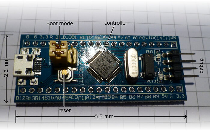
This board is sized 5.3mm × 2.2mm and breadboard compatible. I got mine quite cheap and also undocumented from china. At least i couldn’t find an original from the seller’s site. So i had to do a bit guessing. Luckily most of the boards labeling is just the signal/pin names from the chip. So no need to map from chip pins to a different breakout board numbering scheme.
Board specs:
- Cortex®-M3
- up to: 72Mhz
- ram: 20kb
- flash: 128kb
The jumpers on the board are not labeled. But they are connected to the boot0 and boot1/PB2 (from top to bottom). Both are connected to the stm32 via 100kΩ. The debug header has GND, SWCLK(PA14), SWDIO(PA13) and 3.3V. Reset is also available on as pin R besides the button. The LED is connected from C13 to 3.3V with a 680Ω resistor.
STM32 from scratch, the bare minimum
on 2016-02-20 in stm32-from-scratch
For some future projects i need to bring up a small microcontroller board containing a STM32F103C8T6. But most ARM Cortex-Mx devices are similar for how far this series is going to reach.
Because i like to really know what is running in my microcontroller projects i decided to bring up this device from scratch and document what i needed to do. Where from scratch means i'm allowed to use the basic gnu toolchain (make, g++, ld, as, objcopy), a flash program, the vendor documentation and the register definition headers from STM.
ARM microcontrollers are often said to be complicated and beyond the reach of beginners. I tend to disagree. I started my embedded development with ARM. And i found my trusted gnu toolchain well supported. But i also found big vendor libraries full of cross compiler compatibility and wrappers around simple register manipulation. While these libraries can be a great help if you just want things to be running, they tend to stand in the way of real unterstanding. So here i'm not going to use those libraries.
I made an exception for the hardware register/memory mapped io definitions. Transcibing them from the documentation to C++ code really is just error prone and not very enlightening. For this post i extracted just what is needed from those headers to show how these work. But generelly if the vendor releases them with a truely free license they are nice to use (At least as long as you're no using some C++ meta programming libraries that need definitions in quite a different form. Kvasir comes to mind).
Some of the complexity is also because the ARM ecosystem is a multi vendor ecosystem with actual choice. So much less is hidden in the toolchain, because that is shared among different vendors. Actually having to think about linker scripts is one symptom of this. They do exist for desktop development too, but the toolchain ships with one full of deep knowledge of a well standardized platform. So we tend to ignore them and all the raw power that they contain. Or maybe because the documentation and error handling tends to be a bit rough.
This post details the minimum of c++ code and linker scripts to get the LED on the board to blink. This is actually a bit of code golf. You shouldn't really use code from this post. But it's a good start to have something very minimal to explain and later expand upon.
When starting to bring up a microcontroller the first stop of course is the documentation. In this case consisting of a datasheet(DS5319), a (hardware) reference manual (RM0008), a CPU architecture manual (PM0056) and maybe an errata sheet (learn look at them early to avoid nasty surprises).
Highlights from the datasheet for now are:
- ARM Cortex-M3 CPU, that's what we need to bring up to execute our program.
- Boots with internal 8 MHz RC oscillator selected as clock
- 3.3V with 5V tolerance on many pins, we might need to attach an LED and power to it.
- A block diagram, always handy to have for an quick overview
- The memory map, needed for the linker script
- It has a boot loader mode, so we can get software into the flash without JTAG or similar
As i am using a ready made board with the microcontroller i can ignore most of the pinout for now. Of course i need to find out which pin and thus which
GPIO (general purpose input/output) the LED i want to controll is attached to. The LED is helpfully labeled PC13 which ends up as the port with
index 13 (so zero based counting) of GPIO port C.
All the other details and charateristics are not needed for now. Great 100+ pages i don't need to keep in my head for now.
Ok, now what actually happens when this part is powered on? Well actually, no. In what state is it when is starts to execute code and which code
will it start to execute? The datasheet told me that there is an integrated bootloader, so first i need to know how to enable and disable that.
Section 3.4 "Boot configuration" of the Reference Manual has all i need. There are 2 boot pins (called BOOT0 and BOOT1, but BOOT1 is shared
with a GPIO on the chip i use) that are sampled after reset. For normal boot from embedded flash BOOT0 needs to be pulled to low.
A the datasheet tells me that BOOT0 is pin 35 and a good light and sharp eyes trace that pin to the upper jumper on the board i use (which came completly
without documentation).
With the rom bootloader out of the way i can focus on the environment my early bootup code has to run. ARM Cortex Mx is a very C/C++ friendly architecture so my goal is to boot directly using C++ code. While this is certainly not 100% portable C++ and might even not be actually guaranteed to work with gcc's g++, in pratice this works well.
The boot configuration section also has some information about the initial state of the cpu. But it uses a bit confusing language. So let's refer to the more general documentation. Section 4 of the datasheet contains the memory map in great detail. For now look at the big picture:
- SRAM goes from 0x2000 0000 up
- Flash memory goes from 0x0800 0000 up to 0x0801 FFFF
- Memory from 0x0000 0000 up is aliased depending on the boot pins
ARM memory maps are quite sparse. Bootup state of the cpu is described in the STM Cortex-M3 programming manual. Sections 2.1.1, 2.1.2 and 2.1.3 detail the basic cpu registers and their reset state. The most relevant part is that the initial value of the stack pointer is read from the 32 bit word at 0x00000000 and the initial value of the program counter is read from 0x0000 0004. This is actually the start of the vector table (2.3.4), but for now the other vectors can be ignored. Also it states that the processor starts in privileged(2.3.2) thread mode using the main stack. By the way, the arm stack grows towards lower addresses.
Interrupts are disabled on start. Some arm cores have a memory protection unit (MPU). Section 4.2.6 shows that the reset value of its enable register is off.
So back to the Reference Manual, using BOOT0 pulled low, the addresses starting from 0x0000 0000 are setup to alias 0x0800 0000, that is the main flash area. So that's enough to start writing some code. And some linker configuration. So lets start with the linker script. As i said above the gnu arm toolchain doesn't have special knowledge about specific microcontrollers.
OUTPUT_FORMAT(elf32-littlearm)
OUTPUT_ARCH(arm)
This tells ld that it's going to process arm object files using the elf format as general object file format. The microcontroller of course doesn't use elf, but the elf bits will get stripped off as the very last build step.
MEMORY {
    FLASH : ORIGIN = 0x08000000, LENGTH = 64K
}
The MEMORY command declares memory regions that the linker can use for allocating specific usages. For now we only need one region for the flash part
of the memory map. FLASH is just an identifier to refer to this region later. ORIGIN and LENGTH specify the regions location in the address space.
SECTIONS {
    .vectors : {
        *(.vectors)
    } > FLASH

    .text : {
        *(.text*)
    } > FLASH

}
ELF uses named sections for various parts of code and data. For now the SECTIONS command just instructs ld to put the .vectors section at the
start of the flash filling it with the contents of the .vectors sections of the input files. The second part does similarly with sections whose name
starts with .text, adding them just after the vectors section.
As the flash memory gets aliased to 0x0000 0000 on boot, the vectors section will be readable from 0x0000 0000 and 0x0000 0004 to setup the stack and program counter registers to start the actual program.
On to the C++ code:
void mainFn() {
    // code to follow later
}

extern void (* const vectors[])() __attribute__ ((section(".vectors"))) = {
                (void (*)())0x20000400,
                mainFn,
};
The first part is simple for now. mainFn will be the function where execution starts. But for that to actually happen the vectors table needs
to be setup. That's what the second part does. __attribute__ ((section(".vectors"))) instructs g++ to emit this initialized array into the
section named .vectors to be picked up later by the linker and placed at the very start of the flash section. As C++ is typed and most of the
vector table is later filled with pointers to functions i've choosen to use void (*)() as the basic type of the array. I’ve also made this const
so that matches at c++ level with the final placement of the section in flash. As const implies internal linkage in C++ the extern also is needed
for g++ to actually emit this at C++ level unused data.
Index 0 is the initial value of the stack register. 0x2000 0400 is 1kbyte from the start of the SRAM in the memory map. As stack grows towards lower addresses if the program overflows the stack it will fault, which should be more useful while debugging then just silently corrupting whatever memory happens to come below the stack. 1kbyte should be ok for experimenting, but likely it's much more than needed most programs. Later this will be supplied from the linker. The second value is the address of the function to run on reset, also known as reset handler.
The goal of this simple program is to blink the LED attached for GPIO C13. So on to setting up GPIO port C. Section 9 of the reference manual covers the GPIOs. But this block starts in disabled (i.e. unclocked) state on boot. So Section 7.3 the register part of "reset and clock control" is our first stop. GPIO port C is controlled by the IOP C EN bit in the APB2 EN R register of the RCC. As most peripherial registers are memory mapped in arm this will be a read–modify–write on a memory address.
Mapping all the needed registers oneself doesn't help much in understanding or fine control of the system. So i'll use the vendor provided definition from STM32CubeF1 (i used version 1.2) which are available in BSD (3 clause) licensed form in the directories STM32Cube_FW_F1_V1.2.0/Drivers/CMSIS/Include and STM32Cube_FW_F1_V1.2.0/Drivers/CMSIS/Device/ST/STM32F1xx/Include But for the program in this post i extracted the relevent code to exlpain the general setup of the hardware mapping. The parts needed for enabling the GPIO Port are:
#define     __IO    volatile

typedef struct
{
  __IO uint32_t CR;
  __IO uint32_t CFGR;
  __IO uint32_t CIR;
  __IO uint32_t APB2RSTR;
  __IO uint32_t APB1RSTR;
  __IO uint32_t AHBENR;
  __IO uint32_t APB2ENR;
  __IO uint32_t APB1ENR;
  __IO uint32_t BDCR;
  __IO uint32_t CSR;


} RCC_TypeDef;

#define PERIPH_BASE           ((uint32_t)0x40000000)
#define AHBPERIPH_BASE        (PERIPH_BASE + 0x20000)

#define RCC_BASE              (AHBPERIPH_BASE + 0x1000)

#define RCC                   ((RCC_TypeDef *) RCC_BASE)

#define  RCC_APB2ENR_IOPCEN   ((uint32_t)0x00000010)
So access to memory mapped registers used volatile access to prevent to compiler from any kind of reordering of these accesses. As is usually done
in ARM register definitions all registers of one component are gathered into one struct and a macro is definied that ultimatly ends up as a typecast
of it’s base address to an pointer of this type. Additionally we get a macro that maps bits in the register to values. So the following code in the
mainFn now enables the gpio port component:
RCC->APB2ENR |= RCC_APB2ENR_IOPCEN;
Back to the gpio configuration. Most gpios start up tristated (that is in high impedance mode). This gpio block has 4 bits of configuration for each pin. Thus configuration is split into 2 32-bit registers. The high part of the configuration register contains configuration of output 13. For now i picked any output mode and set it to push-pull mode. Resulting in 0b0011 as configuration. For the rest of the pins floating input mode is selected which is also the reset state. But this way it's a simple set instead of a read–modify–write and the state is more explicitly visible. As the LED's cathod is connected (via a resistor of course) to the GPIO, setting the state of the GPIO to low will activate the LED. One way to set on pin to low is to write to the port bit reset register with the bit corresponding to the pin index set to one. The code (omitting the definition of GPIOC which is similar to how RCC is defined):
    GPIOC->CRH = 0b0100'0100'0011'0100'0100'0100'0100'0100;
    GPIOC->BRR = 1 << 13;
On reset the second line is not strictly needed, because the reset state already has all output data bits of the GPIO as 0. But here i opted to be explicit.
Ok, on to blink the LED. I want 1 Hz and 50% duty cycle. So next we need a 500ms delay. A simple way, when there are no interrupts to add unpredictable additional delay, is just to use a waiting loop. To get the timing right we need to know the exact generated code and how much cycles are taken by each machine instruction. And we need to tell g++ not to optimize away the loop, because a wait loop looks just useless to it.
    int ctr = 1000;
    while (ctr) {
        asm("");
        --ctr;
    }
Apart from the start value for ctr this simple loop is a good delay loop. The asm(""); doesn't emit any code, but g++'s optimizer doesn't considers this asm statement to be removable by optimization, so it’s a easy way to disable code removal. To calculate the right value for ctr we need to look at the generated assembly. I'm using objdump --disassemble here:
  1e:   f44f 737a       mov.w   r3, #1000       ; 0x3e8
  22:   3b01            subs    r3, #1
  24:   d1fd            bne.n   22 <_Z6mainFnv+0x22>
That’s the whole loop, extracted from the 20·ish lines of output from objdump. For most who have read any kind of assembly this looks rather expected. An immediate load of the start value (not part of the loop proper), an substraction of the loop variable and an conditional jump back to the look start. One thing to watch out for when looking at ARM assembly is that the instruction mnemonics used by ARM changed over time(now uses Unified Assembler Language (UAL)), so depending on the tools and documentation it sometimes happens that they mismatch. The subs instruction takes 1 cycle and the bne.n takes 2-4 cycles (e.g. ARM Cortex‑M3 Processor Technical Reference Manual 3.3.1). In simple loops the branch is sufficently easy that in my experience it mostly takes 2 cycles. This all assumes that g++ doesn't start to generated different code. So with the cpu still running on the internal 8MHz clock we get:
        int ctr;
        ctr = (8000000 / 3) / 2;
        // each loop iteration takes 3 cycles to execute.
        while (ctr) {
            asm ("");
            --ctr;
        }
Next step is setting the GPIO to high to disable the LED. The GPIO has a register that allows both setting and resetting individual bits that can be used just like BRR to set the bits: BSRR.
So the final blinking code looks like this:
#include "minsys.h"

void mainFn() {
    RCC->APB2ENR |= RCC_APB2ENR_IOPCEN;
    GPIOC->CRH = 0b0011'0000'0000'0000'0000'0000;
    GPIOC->BRR = 1 << 13;

    while (1) {
        int ctr;
        ctr = (8000000 / 3) / 2;
        // each loop iteration takes 3 cycles to execute.
        while (ctr) {
            asm ("");
            --ctr;
        }
        GPIOC->BRR = 1 << 13;
        ctr = (8000000 / 3) / 2;
        // each loop iteration takes 3 cycles to execute.
        while (ctr) {
            asm ("");
            --ctr;
        }
        GPIOC->BSRR = 1 << 13;
    }
}


extern void (* const vectors[])() __attribute__ ((section(".vectors"))) = {
                (void (*)())0x20000400,
                mainFn,
};
minsys.h here is the minimal definitions extracted from the mbed board headers.
The last step is to actually compile this and upload it to the board to test:
arm-none-eabi-g++ -c -mcpu=cortex-m3 -mthumb --std=c++14 -O2 -fno-rtti -fno-exceptions main.cpp -o main.o
Here -mcpu=cortex-m3 -mthumb tells g++ what cpu the code should be generated for. While -mthumb looks redundant for an cpu that only supports thumb code, g++ requires it nevertheless. I use c++14 mode because it’s constexpr support comes in handy even with embedded development. -fno-rtti and -fno-exceptions disable runtime type information and the complete exception infrastructure in the generated code. This is important because both need runtime support code and that infrastructure is rather large and thus hard (or impossible) to fit into small microcontrollers.
arm-none-eabi-g++ -mcpu=cortex-m3 -mthumb -Tlinkerscript.ld -nostartfiles main.o -o main.elf
Next step is to link the code. -Tlinkerscript.ld specifies the linker script that should be used for linking, replacing ld’s default linker script. In this case i saved linker script in the file linkerscript.ld. -nostartfiles disables the usage of any toolchain provided object files for the entrypoint and start.
The linker generates a fully linked output that still contains elf metainformation like section names and various other bookkeeping data.
arm-none-eabi-objcopy -O binary main.elf main.bin
This metadata is stripped away by objcopy when copying to a binary (or ihex) format. objcopy in this mode produces a file that starts with the data of the loaded section with the lowest load address and pads space between sections with zero bytes. In this example there are no gaps between the sections.
A hexdump of the result still fits nicely in a few lines:
000000 00 04 00 20 09 00 00 08 0b 4b 70 b4 4f f4 00 54
000010 19 46 22 46 09 4d 4f f4 40 16 a8 69 40 f0 10 00
000020 a8 61 5e 60 5c 61 06 4b 01 3b fd d1 04 4b 4a 61
000030 01 3b fd d1 0a 61 f6 e7 00 10 01 40 00 10 02 40
000040 55 58 14 00
Well not that we are going to analyse this. But we see that this generated 68 bytes of binary.
The binary can now be uploaded to flash. I use stm32flash which is just an apt install stm32flash away with debian. For this we need to set the board to bootloader mode, so pull boot0 up to 3.3V and push reset. Then stm32flash should be able to detect the controller using an 3.3V or 5V logic level serial interface.
$ stm32flash /dev/ttyUSB1
stm32flash 0.4

http://stm32flash.googlecode.com/

Interface serial_posix: 57600 8E1
Version      : 0x22
Option 1     : 0x00
Option 2     : 0x00
Device ID    : 0x0410 (Medium-density)
- RAM        : 20KiB  (512b reserved by bootloader)
- Flash      : 128KiB (sector size: 4x1024)
- Option RAM : 16b
- System RAM : 2KiB
To flash and run use:
stm32flash -w main.bin /dev/ttyUSB1
stm32flash -g0 /dev/ttyUSB1
Now the board should blink it’s LED.
For full code see here