Interrupts
on 2016-04-24 in stm32-from-scratch
In this part i am going to add a simple example for an interrupt. And some infrastructure to easily hook up interrupt handlers.
In the first part i added only a minimal vector table needed for getting the code to run. Of course the cpu has more exceptions that it expects to be described in the vector table. So it’s a good idea to fill the table with defined function pointers.
 extern char __stack_end;
 extern void (* const vectors[])() __attribute__ ((section(".vectors"))) = {
                 (void (*)())&__stack_end,
                 Reset_Handler,
+                NMI_Handler,
+                HardFault_Handler,
+                MemManageFault_Handler,
+                BusFault_Handler,
+                UsageFault_Handler,
+                0,
+                0,
+                0,
+                0,
+                SVCall_Handler,
+                DebugMonitor_Handler,
+                0,
+                PendSV_Handler,
+                Systick_Handler,
+                Irq0_Handler,
+                Irq1_Handler,
// ...
Section 2.3 (Exception Model) of the STM Cortex-M3 programming manual describes the exception model and contents of the vector table. The vector tables starts with the initial stack pointer and reset handler as setup in the first post. This is followed by 14 words defined by the arm cortex m system architecture. All that are set to 0 are documented as "reserved" in the reference manuals and i couldn’t find for what they might be reserved.
- NMI
- Non maskable interrupt: can be triggered by software or external interrupt (e.g. clock security system)
- HardFault
- Last resort exception handler
- MemManageFault
- memory access rejected by memory protection unit (MPU)
- BusFault
- bus error while accessing memory
- UsageFault
- e.g. undefined instruction, unaligned access, division by zero (not all enabled by default)
- SVCall
- Call to privileged code via `svc` instruction
- DebugMonitor
- used with certain debugging techniques
- PendSV
- Can be triggered using the “interrupt control and state register” from privileged code
- Systick
- Interrupt for the Systick timer common to all cortex-m
Most of the arm defined exceptions are disabled in the reset state and instead the hard fault is executed. The NMI is always enabled, except when the last NMI execution caused to processor to lockup.
The IrqN_Handler·s are vendor defined peripheral interrupts. The assignment of those to are described in Section 10 (Interrupts and events) of the hardware reference manual.
So what happens when an interrupt is triggered? The process starts with some component detecting that an interrupt should be raised. This can be a part of the hardware via an interrupt line or a part of the software via a bit in a special register.
The interrupt request is signaled to the Nestable Vectored Interrupt Controller (NVIC) which is a part of the arm defined core peripherals. It buffers all interrupt requests in it’s interrupt pending register, even if the interrupt source later is disabled it’s bit in the pending register is not reset. It only uses this pending state if the interrupt is also enabled, if not it just keeps pending but doesn’t have a further effect until enabled. The NVIC tracks which interrupt is activly serviced by the cpu.
Each interrupt is assigned a priority. Most priorities are configurable by software, only Reset, NMI and hard fault have fixed priorities higher than any other interrupt. Among themselves Reset has the highest priority, followed by NMI and hard fault. Interrupts have higher priority if their priority value is a lower number.
The NVIC looks at the interrupt with the highest priority. If the CPUs PRIMASK, FAULTMASK and BASEPRI setting allow execution of the interrupt and if the CPU is serving no interrupt or a interrupt of strictly lesser priority it will initiate processing of the interrupt. In this process if stack alignment is needed (STKALIGN in SCB_CCR set and stack not aligned to 8 bytes) the stack is aligned and bit 9 (reserved) in PSR is set. Next the cpu will push registers R0-R3,R12,LR,PC and PSR to the stack that was active before serving the interrupt and then activate the main stack in case the process stack was active before. In this tutorial everything runs on the main stack.
The cpu will then set LR to a special class of values (EXC_RETURN) used later when returning from the interrupt. Also the currently executed interrupt is stored in the IPSR cpu register. The cpu then resumes execution on the first instruction of the interrupt handler as indicated in the vector table.
This whole procedure means that the interrupt looks to the called handler like a normal C calling convention abiding function call with no arguments from a piece of code running in privileged mode on the main stack. Thus we can use normal C++ functions for interrupt handling. All registers not saved by interrupt entry will be saved by the code generated for the function if the function needs to write to them. As i said before, cortex m is very C friendly.
When the interrupt handler returns it will load the special value from the LR register as new execution address. This will be detected by the cpu (if done via a supported instruction for interrupt return and while processing an interrupt) and the following special handling will be triggered. The lower 5 bits of the LR value encode if it was a nested interrupt and which stack was in use when the interrupt was started. The cpu then switches to the stack that was active before the interrupt and pops of the saved register contents and if needed undoes the stack alignment (controlled by bit 9 of the stacked PSR). For some long running instructions with side effects (LDM and STM) the cpu has special logics to resume partially executed instructions.
In most cases an interrupt handler needs to explicitly acknowledge the cause of the interrupt, because many interrupts are level triggered which means as soon as the handler returns that would be called again if the handler didn’t acknowledge them.
In cortex m cpus there are also a few of mostly software transparent optimisations like that when an interrupt of higher priority arrives while preparing for an interrupt the higher priority interrupt replaces the previous interrupt (so called late arriving optimisation) and that if another interrupt needs to be executed when the current one is finished it doesn’t need to execute a complete unstack/restack cycle (tail-chaining).
Ok, now we know that the cpu architecture does a lot work to allow application code to run like a normal function call even if called as interrupt handler. So a simple default interrupt handler for unexpected interrupts looks like this:
void Default_Handler() {
    while (true) {
        ;
    }
}
This is not really useful because it just catches the cpu in an endless loop. But for simple projects this is a safe state. In other situations an unexpected interrupt might be better served with shuting down hardware and maybe triggering a reset. But let’s work with this simple default handler:
void Default_Handler();

extern "C"
void Default_HandlerWrapper() {
    Default_Handler();
}
#define DEFINE_HANDLER(name) void name ## _Handler(void) __attribute__ ((weak, alias("Default_HandlerWrapper")));
The main idea here is to have all possible exception handlers weakly aliased to the default handler. The linker will pick either the default handler or a strongly defined function defined in a different file as the value to put into the vector table.
First i need a local wrapper for the default handler because the alias attribute needs a symbol defined in the same compilation unit. Then i’m using the preprocessor here to keep repeated code at a minimum and seperate different aspects a bit. The name of the aliased function is contructed from the macro parameter with an appended _Handler.
#define Irq0_Handler  WWDG_Handler
#define Irq1_Handler  PVD_Handler
// ...
#define Irq25_Handler TIM1_UP_Handler
// ...
#define Irq67_Handler USB_FS_Handler
In this file we need to order the exception handlers in the vector array by number. I decided
to use a layer of preprocessor macros to keep the dependance on their concrete use minimal.
So i setup a series of macros that just map the vendor specific mapping of irq number to the
cleartext name. So later it’s easy to ensure that the vector array is correctly build and
it’s easy to check the mapping from irq number to function name because by construction the
correct number is right beside the cleartext name. This needs to be placed before any other
usage to the IrqN_Handler names is made in this file. As the compiler after preprocessing
sees the cleartext names the macros are only needed in the file containing the
DEFINE_HANDLER calls and the vector array.
DEFINE_HANDLER(NMI)
DEFINE_HANDLER(HardFault)
DEFINE_HANDLER(MemManageFault)
DEFINE_HANDLER(BusFault)
DEFINE_HANDLER(UsageFault)
DEFINE_HANDLER(SVCall)
DEFINE_HANDLER(DebugMonitor)
DEFINE_HANDLER(PendSV)
DEFINE_HANDLER(Systick)
DEFINE_HANDLER(Irq0)
DEFINE_HANDLER(Irq1)
// ...
DEFINE_HANDLER(Irq67)
This code setups the alias for every exception. It also uses the macro layer so it’s easy to maintain.
That’s it for the preliminaries and intrastructure. Let’s revisit the blinking code but using a timer interrupt:
void TIM1_UP_Handler() {
    // Clear interrupts
    TIM1->SR = 0;
    GPIOC->ODR ^= 1 << 13;
}
I’ve chosen timer TIM1 for this post. It has a dedicated update interrupt that is invoked when it’s counter is reset. First the code acknowledges all conditions of the timer. In real code this acknowledge should likely be more selective but what needs to be acknowledged is highly application dependent. After that the handler flips the bit corresponding to the LED in the output data register of the gpio block. Keep in mind that this reads the register, modifies it and replaces the register content with the new value. Thus this is not an atomic operation.
Next the timer needs to be setup:
void initTimer() {
    RCC->APB2ENR |= RCC_APB2ENR_TIM1EN;

    RCC->APB2RSTR |= RCC_APB2RSTR_TIM1RST;
    RCC->APB2RSTR &= ~RCC_APB2RSTR_TIM1RST;

    TIM1->DIER = TIM_DIER_UIE;
    TIM1->CNT = 1;
    TIM1->ARR = 732 / 2;
    TIM1->PSC = 0xffff;
    TIM1->CR1 = TIM_CR1_CEN;

    // Clear interrupts
    TIM1->SR = 0;

    NVIC_EnableIRQ(TIM1_UP_IRQn);
    NVIC_SetPriority(TIM1_UP_IRQn, 15);
}
This is fairly straight forward. The first three lines enabled and reset the timer.
TIM_DIER_UIE enables the interrupt generation for update events. Then the initial
counter (CNT), the reload value (ARR) and the prescaler (PSC) as set so that the timer
will trigger approximately twice per second (48MHz / (0xffff+1) / 732 / 2 = 0.50028… Hz).
Timer TIM1 runs in this case with full APB2 frequency (see clocktree, APB2 divider is set
to 1x so the additional divider for TIM1 is disabled).
After the timer is setup, it get’s enabled (CR1_CEN) and all pending interrupts acknowledged. Then the interrupt is enabled in the NVIC and it’s priority is set to the lowest value. I’m using function from the arm CMSIS headers here, because they for once do the straight forward thing.
We just need to use the code now:
        initTimer();
        while (1) {
            ;
        }
After starting the timer all that’s left is loop waiting for interrupts.
When you try to run this programm please be sure to use a hardware reset without bootloader.
Starting using stm32flash -g0 will possibly not work at this point.
I encountered a very strange effect when first trying to enable interrupts on this system.
In the end the explaination was that stm32flash -g0 has two possible modes of operation.
If the pin BOOT0 still is pulled high to select the bootloader it will just jump to the
reset handler of the code in the flash, but the remapping of the low address space still is
in place. On the other hand if BOOT0 is no longer pulled high the remapping will be as
after a clean reset. I can only guess that that is what happens. If possible it triggers a
hardware reset, otherwise is does a partial emulation. In case of the emulation the end
result is that the exception vector of the bootloader is still in place and interrupts fail
horribly. So beware that the environment for code started from the bootloader can subtly
differ from a real reset.
In this case there is an easy fix:
    extern uint32_t vectors;

    SCB->VTOR = (uint32_t)&vectors;
It explicitly sets the NVIC to use the vectors from their address in flash instead of relying on the remapping. With this code added interrupts also work reliable when starting using the bootloader.
Another potential reliablity problem with the current code is that the gpio is accessed with a non atomic read-modify-store cycle. If this cycle is interrupted by an interrupt with higher priority that also modifies this register some modifications will be lost.
One solution would be to block interrupts using PRIMASK before the modification and to
reenable them after the modification is complete. Another possibility is to use the
bitbanding engine available in cortex m3 and higher. It abstracts atomic bit set and clear
into a memory mapped peripherial. For supported ranges of SRAM and device registers for
every bit there is a 32bit word where the least significant bit is mapped to the bit in the
original memory region. This is still implemented as a read-modify-write cycle so it
should not be used on registers where writing the current value would have any
side-effects (e.g. write 1 to clear bits, etc). But this is atomic with regard to cpu
and even DMA accesses from the system. So it‘s a nice way to implement atomic bit
operations. It does not support toggeling a bit atomically. So using it to toggle a
bit uses 2 reads and one write and is not atomic with regard to this one bit. So if any
other code can also change the value of the bit some other protection will be needed.
template <unsigned reg, unsigned bit>
constexpr __IO uint32_t& bit_band_alias_impl() {
    static_assert((0x40000000 <= reg && reg <= 0x400FFFFF)
                  || (0x20000000 <= reg && reg <= 0x200FFFFF), "reg outside bitbandable area");
    static_assert(bit <= 31, "bit must be <= 31");

    return reg >= 0x40000000 ? (*((uint32_t*)(0x42000000 + (reg - 0x40000000) * 32 + bit * 4)))
                             : (*((uint32_t*)(0x22000000 + (reg - 0x20000000) * 32 + bit * 4)));
}
#define bit_band_alias(reg, bit) bit_band_alias_impl<(unsigned)&(reg), bit>()
This combination of a macro and an constexpr template function allows safe compile time
checked and calculated access via bit banding. The two static_assert ensure that no out
of range input can accidentially slip through. Templates doen’t allow pointers to calculated
memory locations as non type parameters. So a macro is needed to hide the typecast.
Usage is:
bit_band_alias(GPIOC->ODR, 13) ^= 1;
One last improvement is to save power in the idle loop. If the code just waits for an interrupt the wfi (wait for interrupt) instruction can be used to enter sleep mode while waiting for the interrupt:
         while (1) {
-            ;
+            __WFI();
         }
In my setup this saves around 20mA. So it’s an easy way to reduce power consumtion without much work.
Code as always available as git commits.
STM32 PLL and Crystal Oscillator
on 2016-04-11 in stm32-from-scratch
After some more toolchain oriented posts in this series, let’s get back to the actual micro controller. Since the first part of this series the sample code is running using the default 8MHz internal clock. In this part I'm going to enable the external oscillator and use the PLL (phase locked loop) to scale it’s frequency up to run the microcontroller at a faster pace (and more energy consumption, of course).
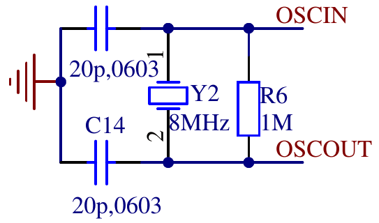
The board i’m using has an 8MHz quarz crystal and the needed passives connected to he external oscillator pins of the microcontroller.
    // enable high speed external oscillator
    RCC->CR = (RCC->CR & ~RCC_CR_HSEBYP) | RCC_CR_HSEON;
    while (!(RCC->CR & RCC_CR_HSERDY)) {
        ;
    }
The first step is to enable the oscillator circuit by setting RCC_CR_HSEON. RCC_CR_HSEBYP would
enable to use an external clock without the oscillator circuit so we ensure that it is disabled.
The while loop waits until the oscillator circuit has a stable frequency by waiting for
RCC_CR_HSERDY to be asserted by the hardware. This HSE clock is now ready to be used by other
parts in the clock tree.
To run the microcontroller at a higher frequency the the next part is the PLL (phase locked loop). I use it to multiply the output frequency of the HSE to get a 48MHz clock to run the microcontroller.
    // init pll
    int pllmul = 6;
    RCC->CFGR = (pllmul-2) << 18 | RCC_CFGR_PLLSRC | RCC_CFGR_PPRE1_DIV2;
    RCC->CR |= RCC_CR_PLLON;

    while (!(RCC->CR & RCC_CR_PLLRDY)) {
        ;
    }
The PLL multiplier is encoded with an offset of 2, so I prefer to put the multiplier as number
into a variable and apply the offset seperately while constructing the register value. The PLL
can use either the internal 8MHz oder the HSE clock as input RCC_CFGR_PLLSRC selects HSE.
This will output a 48 (8 * 6) MHz clock. The system clock is used to derive various other clocks.
Of of these clocks is the APB1 clock. This clock may not exceed 36 MHz. To prepare for using the
output of the PLL as system clock, the divider for APB1 needs to be set to 2 (RCC_CFGR_PPRE1_DIV2)
so i will only get a safe 24MHz. After setting RCC->CFGR the code enabled the PLL (RCC_CR_PLLON)
and again waits for it to stabilize by polling for RCC_CR_PLLRDY.
The next code is not strictly needed. But when using the serial port to debug it‘s useful to make sure that all data is send before changing the system clock to avoid garbled output. If the serial port was not in use before the frequency change it shouldn‘t delay startup by more than a few cycles.
    if (RCC->APB2ENR & RCC_APB2ENR_USART1EN) {
        // if usart1 is clocked wait to drain possible debugging infos.
        while ((USART1->SR & (USART_SR_TXE | USART_SR_TC)) != (USART_SR_TXE | USART_SR_TC)) {
            ;
        }
    }
Finally it’s time to actually switch to the clock generated by the PLL.
    // switch sysclock to pll
    RCC->CFGR |= RCC_CFGR_SW_PLL;

    // wait for ack
    while ((RCC->CFGR & RCC_CFGR_SWS) != RCC_CFGR_SWS_PLL) {
        ;
    }
And of course wait for the switch to be acknowledged by the hardware. And that’s it. The microcontroller is now switched to 48 MHz. Of course the serial code and the delay while blinking have the frequency hardcoded. So we need to change those to use 48 MHz instead of 8 MHz for calculations.
Code as always available as git commits.
1. STM32 from scratch, the bare minimum
2. STM32 from scratch, the hardware
3. STM32 from scratch, serial
4. Makefile for embedded projects
5. Enabling C/C++ features
6. Heap, malloc and new
8. Interrupts
Heap, malloc and new
on 2016-04-10 in stm32-from-scratch
Sometimes dynamic memory allocation is needed. While often allocating memory statically leads to a more robust system, it’s not always possible within the contraints of the hardware.
In microcontrollers with a simple memory map of only one RAM area, the heap is just the part of the RAM that is not used by anything else in the linker script. So we can just add this after the last section that is put into RAM (.bss in this case):
+    __heap_start = .;
+    __heap_end = ORIGIN(RAM) + LENGTH(RAM);
+
+    /* Don't place any sections that are actually used on target system after the heap without adjusting _heap_end above */
In a sense that‘s all that needs to interact closely with the toolchain. Using __head_start and
__heap_end you can implement you own allocator. If you call your allocation function malloc
gcc does some optimizations based on builtin assumsations about functions from the C standard, so it
might optimize out calls when you don‘t expect.
As i don‘t usually use dynamic memory allocation i tend to resort to use the malloc implementation from newlib in it’s nano configuration that is shipped with the toolchain.
To enable the nano configuration of the libc we need to pass -specs=nano.specs in the final link
command. Newlib expects a traditional unix like sbrk function for heap size management.
/* needed for malloc in newlib */

extern "C" void* _sbrk(int increment);
void* __attribute__((weak)) _sbrk (int increment) {
    extern char __heap_start;
    extern char __heap_end;

    static void* __heap_top = &__heap_start;

    void *new_heap_top;
    if (__builtin_add_overflow((intptr_t)__heap_top, increment, (intptr_t*)&new_heap_top)) {
        return (void*)-1;
    }
    if (!(&__heap_start <= new_heap_top && new_heap_top <= &__heap_end)) {
        return (void*)-1;
    }

    void* old_top = __heap_top;
    __heap_top = new_heap_top;

    return old_top;
}
_sbrk is a fairly simple wrapper around a static variable that keeps track of the part of the
heap already handed out to the malloc implementation, while checking that it stays inside of the
heap. It is careful about integer overflows and uses the compiler intrinsic __builtin_add_overflow
(needs a recent gcc to work).
With this bit of support code the newlib malloc should be usable. Or an other simple malloc
implementation that uses sbrk.
With an working malloc implementation the new operator also works. Because we‘re using c++ without
exceptions remember that it spells as new(std::nothrow) and needs #include <new>
The support code is included here
1. STM32 from scratch, the bare minimum
2. STM32 from scratch, the hardware
3. STM32 from scratch, serial
4. Makefile for embedded projects
5. Enabling C/C++ features
7. STM32 PLL and Crystal Oscillator
8. Interrupts