STM32 PLL and Crystal Oscillator
on 2016-04-11 in stm32-from-scratch
After some more toolchain oriented posts in this series, let’s get back to the actual micro controller. Since the first part of this series the sample code is running using the default 8MHz internal clock. In this part I'm going to enable the external oscillator and use the PLL (phase locked loop) to scale it’s frequency up to run the microcontroller at a faster pace (and more energy consumption, of course).
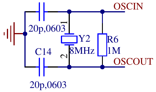
The board i’m using has an 8MHz quarz crystal and the needed passives connected to he external oscillator pins of the microcontroller.
    // enable high speed external oscillator
    RCC->CR = (RCC->CR & ~RCC_CR_HSEBYP) | RCC_CR_HSEON;
    while (!(RCC->CR & RCC_CR_HSERDY)) {
        ;
    }
The first step is to enable the oscillator circuit by setting RCC_CR_HSEON. RCC_CR_HSEBYP would
enable to use an external clock without the oscillator circuit so we ensure that it is disabled.
The while loop waits until the oscillator circuit has a stable frequency by waiting for
RCC_CR_HSERDY to be asserted by the hardware. This HSE clock is now ready to be used by other
parts in the clock tree.
To run the microcontroller at a higher frequency the the next part is the PLL (phase locked loop). I use it to multiply the output frequency of the HSE to get a 48MHz clock to run the microcontroller.
    // init pll
    int pllmul = 6;
    RCC->CFGR = (pllmul-2) << 18 | RCC_CFGR_PLLSRC | RCC_CFGR_PPRE1_DIV2;
    RCC->CR |= RCC_CR_PLLON;

    while (!(RCC->CR & RCC_CR_PLLRDY)) {
        ;
    }
The PLL multiplier is encoded with an offset of 2, so I prefer to put the multiplier as number
into a variable and apply the offset seperately while constructing the register value. The PLL
can use either the internal 8MHz oder the HSE clock as input RCC_CFGR_PLLSRC selects HSE.
This will output a 48 (8 * 6) MHz clock. The system clock is used to derive various other clocks.
Of of these clocks is the APB1 clock. This clock may not exceed 36 MHz. To prepare for using the
output of the PLL as system clock, the divider for APB1 needs to be set to 2 (RCC_CFGR_PPRE1_DIV2)
so i will only get a safe 24MHz. After setting RCC->CFGR the code enabled the PLL (RCC_CR_PLLON)
and again waits for it to stabilize by polling for RCC_CR_PLLRDY.
The next code is not strictly needed. But when using the serial port to debug it‘s useful to make sure that all data is send before changing the system clock to avoid garbled output. If the serial port was not in use before the frequency change it shouldn‘t delay startup by more than a few cycles.
    if (RCC->APB2ENR & RCC_APB2ENR_USART1EN) {
        // if usart1 is clocked wait to drain possible debugging infos.
        while ((USART1->SR & (USART_SR_TXE | USART_SR_TC)) != (USART_SR_TXE | USART_SR_TC)) {
            ;
        }
    }
Finally it’s time to actually switch to the clock generated by the PLL.
    // switch sysclock to pll
    RCC->CFGR |= RCC_CFGR_SW_PLL;

    // wait for ack
    while ((RCC->CFGR & RCC_CFGR_SWS) != RCC_CFGR_SWS_PLL) {
        ;
    }
And of course wait for the switch to be acknowledged by the hardware. And that’s it. The microcontroller is now switched to 48 MHz. Of course the serial code and the delay while blinking have the frequency hardcoded. So we need to change those to use 48 MHz instead of 8 MHz for calculations.
Code as always available as git commits.
1. STM32 from scratch, the bare minimum
2. STM32 from scratch, the hardware
3. STM32 from scratch, serial
4. Makefile for embedded projects
5. Enabling C/C++ features
6. Heap, malloc and new
8. Interrupts
About
Related
- Interrupts
- STM32 PLL and Crystal Oscillator
- Heap, malloc and new
- Enabling C/C++ features
- Makefile for embedded projects
- STM32 from scratch, serial
- STM32 from scratch, the hardware
- STM32 from scratch, the bare minimum