Makefile for embedded projects
on 2016-02-28 in stm32-from-scratch
Remembering or copying the build commands isn't going to be a usable way to build the example project in this series. So we need a makefile to automate this task. While make isn't the nicest tool it's basic working is well understood and it's still the defacto standard.
This will not be a tutorial for make. But i try to explain at least some basic points. First lets start with a makefile that just replicates what we previously did manually. Adding support for C and assembler files for completeness.
C_SRC =

CXX_SRC = main.cpp

ASM_SRC =

DEFINES =

INCLUDEDIRS = -iquote . -I common/stm_include -I common/cmsis_include

PROJECT = minblink

LD_SCRIPT = linkerscript.ld
The first part is the section that defines the variables which contain the source files to process and similar project specific configuration. It starts with the variables for all the source files: C_SRC for plain c files, CXX_SRC for c++ files and ASM_SRC for assembler source files(using .S as file extension).
Alternativly you can move up the OBJ_FILES line and add the resulting .o files there directly without the code to replace the source extensions by .o. In that case you can remove the *_SRC lines. But as this is setup to output everything in out/ you either need to add that explicitly or keep the transformation with addprefix.
After that are project global settings. PROJECT defines the name of the output files. INCLUDEDIRS specifies the gcc/g++ parameters that relate to the include file directories. DEFINES allows specifing macros that should be defined using the usual -DVAR=VALUE syntax. LD_SCRIPT specifies the name of the linker script to use.
TARGET = arm-none-eabi-

OUT=out

CC = $(TARGET)gcc
CXX = $(TARGET)g++
AS = $(TARGET)gcc -x assembler-with-cpp
OBJCOPY = $(TARGET)objcopy
This section defines the output path and shortcut variables for all used toolchain components.
CPUFLAGS = -mcpu=cortex-m3 -mthumb
COMMONFLAGS = $(CPUFLAGS) -MD -MP -MF $(@:.o=.d) $(DEFINES)

CFLAGS = $(COMMONFLAGS) -O2 \
         -std=gnu99 $(INCLUDEDIRS)

CXXFLAGS = $(COMMONFLAGS) -O2 \
         -fno-rtti -fno-exceptions \
         -std=gnu++14 $(INCLUDEDIRS)

ASFLAGS = $(COMMONFLAGS) $(INCLUDEDIRS)

LDFLAGS = $(CPUFLAGS) -T$(LD_SCRIPT) -nostartfiles
-mcpu=cortex-m3 -mthumb -O2 -fno-rtti -fno-exceptions --std=c++14 are the g++ commandline options from the first part. The linker options are the same too.
New is -MD -MP -MF $(@:.o=.d). It instructs gcc to output a file with all dependencies of the currently compiled source in a format that is directly includable in a makefile. This is needed for automatically rebuilding the affected object files when a included header file is changed.
OBJ_FILES = $(addprefix $(OUT)/, $(notdir $(ASM_SRC:.S=.o)))  \
            $(addprefix $(OUT)/, $(notdir $(C_SRC:.c=.o)))    \
            $(addprefix $(OUT)/, $(notdir $(CXX_SRC:.cpp=.o)))
DEPS = $(OBJ_FILES:.o=.d)
Here all source files from the variables defined at the beginning are gathered and transformed into the object file names that will generated for them. These are used as dependencies for linking. Also for make to automate rebuilding objects when included files change make needs files with dependency information. So DEPS is a list of all these dependency files.
# unconditionally ensure output directory
$(shell test -d $(OUT) || mkdir $(OUT))
It’s needed later. So make sure it exists.
all: $(OUT)/$(PROJECT).bin

clean:
    rm -f $(OUT)/*
Define the default target all that just depends on the output of the objdump below. And also define a clean target that just removes all files from out/.
$(OUT)/%.o: %.c Makefile
    @echo CC $<
    @$(CC) -c $(CFLAGS) $< -o $@

$(OUT)/%.o: %.cpp Makefile
    @echo CXX $<
    @$(CXX) -c $(CXXFLAGS) $< -o $@

$(OUT)/%.o: %.S Makefile
    $(AS) -c $(ASFLAGS) $< -o $@
Rules for to transform all supported kinds of source to object files.
$(OUT)/$(PROJECT).elf: $(OBJ_FILES) Makefile $(LD_SCRIPT)
    $(CXX) $(LDFLAGS) $(OBJ_FILES) -o $@

$(OUT)/$(PROJECT).bin: $(OUT)/$(PROJECT).elf Makefile
    $(OBJCOPY) -O binary $< $@
These are the linking and objcopy step for the very first post in this series.
-include $(DEPS)
It’s traditional to add the include for the dependency files at the end.
Now i like to add more features to help understanding my code and to avoid possible problems.
@@ -23,6 +24,6 @@
 OBJCOPY = $(TARGET)objcopy

 CPUFLAGS = -mcpu=cortex-m3 -mthumb
-COMMONFLAGS = $(CPUFLAGS) -MD -MP -MF $(@:.o=.d) $(DEFINES)
+COMMONFLAGS = $(CPUFLAGS) -g -ggdb3 -Wa,-amhlsd=$(@:.o=.lst)  -MD -MP -MF $(@:.o=.d) $(DEFINES)

 CFLAGS = $(COMMONFLAGS) -O2 \
Generation of debug information (-g -ggdb3) is always a good idea. Even without an debug cable for the used hardware it allows running tools like pa-hole that use debug information for further analysis.
The other part (-Wa,-amhlsd=$(@:.o=.lst)) generates a assembler listing files with annotations for every source file. I tend to look into these quite a bit when working on low-level code. While the compiler is free to produce different code, it helps me quite a bit with understanding where i might have parts in my code that are not supposed to be that way. For example it’s quite easy to constrain the compiler from doing useful and safe optimisations, seeing the assembler often leads to a easy fix back in the C++ code.
@@ -26,11 +26,13 @@ CPUFLAGS = -mcpu=cortex-m3 -mthumb
 COMMONFLAGS = $(CPUFLAGS) -MD -MP -MF $(@:.o=.d) $(DEFINES)

 CFLAGS = $(COMMONFLAGS) -O2 \
-         -std=gnu99 $(INCLUDEDIRS)
+         -Wall -Werror=strict-prototypes -Wextra -Werror=return-type \
+         -std=gnu99 -fstack-usage -fverbose-asm $(INCLUDEDIRS)

 CXXFLAGS = $(COMMONFLAGS) -O2 \
+         -Wall -Wextra  -Werror=return-type \
          -fno-rtti -fno-exceptions \
-         -std=gnu++14 $(INCLUDEDIRS)
+         -std=gnu++14 -fstack-usage -fverbose-asm $(INCLUDEDIRS)

 ASFLAGS = $(COMMONFLAGS) $(INCLUDEDIRS)
Also a good idea is to enable warnings and even promote some warnings to errors.
-Werror=strict-prototypes(C only): Yes, prototypes without argument specifications should never happen.-Werror=return-type: Not returning a value from a function declared to have one is bug, not just a warning.-Wall -Wextra: enable useful warnings and errors.-fstack-usage: Let the compiler calculate stack usage for every function.-fverbose-asm: Output more information in the assembler listings.
-LDFLAGS = $(CPUFLAGS) -T$(LD_SCRIPT) -nostartfiles
+LDFLAGS = $(CPUFLAGS) -T$(LD_SCRIPT) -nostartfiles -g \
+          -Wl,-Map=$(OUT)/$(PROJECT).map,--cref -Wl,--print-memory-usage -Wl,--warn-common
-Wl,-Map=$(OUT)/$(PROJECT).map,--cref: instruct the linker to generate a Mapfile with cross reference table.-Wl,--print-memory-usage: Often there is a need to keep an eye on the size of the program to still fit into the hardware’s limits. This prints a summary of the used space as assigned by the linker. (At the time of writing this needed a fairly recent version of binutils, if you have trouble you might need to remove it)-Wl,--warn-common: Warn about sloppy usage of "extern".
OBJDUMP = $(TARGET)objdump
-all: $(OUT)/$(PROJECT).bin
+all: $(OUT)/$(PROJECT).bin $(OUT)/$(PROJECT).lss $(OUT)/$(PROJECT).dmp
$(OUT)/$(PROJECT).lss: $(OUT)/$(PROJECT).elf Makefile
    $(OBJDUMP) -Slw $< > $@

$(OUT)/$(PROJECT).dmp: $(OUT)/$(PROJECT).elf
    $(OBJDUMP) -x --syms $< > $@
Generates some additional information that can help when trying to find out how much space is used by different parts of the program (.lss and .map) and what is actually included in the final linked program.
For full code see here
1. STM32 from scratch, the bare minimum
2. STM32 from scratch, the hardware
3. STM32 from scratch, serial
5. Enabling C/C++ features
6. Heap, malloc and new
7. STM32 PLL and Crystal Oscillator
8. Interrupts
STM32 from scratch, serial
on 2016-02-23 in stm32-from-scratch
In the first part of this series i detailed how to blink an LED. That’s nice and usually the first thing i try to get to work when bringing up a microcontroller. But it doesn‘t really allow much data to be communicated. So it’s always good to get the serial port to work to do some good classic printf style debugging and explorations.
The serial port in the STM32F103 series doesn't have an internal FIFO buffer. So it’s not really for quick debugging without altering the timing of the running code to much. But for now a simple implementation without interrupts that just waits for the previous byte to be fully transmitted is ok. That’s fairly easy to achive.
But let’s stop using an minimal header file with just hand selected parts of the register definitions. That’s just too boring.
So from this point on i use the headers from STM32CubeF1 (i used version 1.2).
I copied the the files from STM32Cube_FW_F1_V1.2.0/Drivers/CMSIS/Include to common/cmsis_include and from
STM32Cube_FW_F1_V1.2.0/Drivers/CMSIS/Device/ST/STM32F1xx/Include to common/stm_include and added -I common/stm_include -I common/cmsis_include to the compilation command.
void setup_serial(int baud) {
    RCC->APB2ENR |= RCC_APB2ENR_USART1EN;
    int divider = 8000000 / (16 * baud);

    USART1->CR1 = USART_CR1_UE | USART_CR1_TE;
    USART1->CR2 = 0;
    USART1->CR3 = 0;
    USART1->BRR = divider << 4;

    RCC->APB2ENR |= RCC_APB2ENR_IOPAEN;
    GPIOA->CRH |= GPIO_CRH_MODE9_1 | GPIO_CRH_CNF9_1;
    GPIOA->CRH &= ~(GPIO_CRH_CNF9_0 | GPIO_CRH_MODE9_0);
}
Of course the serial port needs some setup. As usual we need to enable the clock before doing anything else. The serial port in the STM32103 chips has lots of strange and wonderful features. But it also does the plain boring 8N1 (8bit, no parity, 1 stop bit) serial communication we need. The details are documented in Chapter 27 of the reference manual.
Next we need to calculate the parameters for clock generation. USART1 is connected to the PCLK2 clock. Looking at the clock tree we see that it’s derived from HCLK (the core cpu clock) via the APB1 prescaler. The reset value of RCC->CFGR[PPRE1] sets this prescaler to pass the clock on undivided. The serial peripheral has a fractional baud rate generator that is setup in units of 1/16 of the input frequency. Thus the baud rate is result of the PCLK2 / baud division is further divided by 16.
The control registers all have reset values of 0. The only bits that need to be altered are uart enable (UE) and transmit enable (TE). The rest defaults to usable values.
Next we need to enable routing the serial signals. The serial transmit is connected to pin A9. So we first enable GPIO port A. Then set index 9 to be a low speed push-pull output for the 'alternate function', which is the serial port in this case. If you also want to receive on the serial line you would need to make sure PA10 is configured as input of suitable type.
bool serial_writebyte_wait(unsigned char val) {
    while ((USART1->SR & USART_SR_TXE) == 0) ;
    USART1->DR = val;
    return 1;
}

void serial_writestr(const char* s) {
    for (const char*ch = s; *ch; ch++) {
        serial_writebyte(*ch);
    }
}
After calling this initialization, we can start writing data to the serial port. Because the hardware doesn't have a FIFO buffer we will most likely loose output when just writing without checking if the last byte written is still waiting to be transfered to the output shift register. Therefor a busy loop ensures that the serial part is prepared to take an new output byte by waiting for the “transmit data register empty” bit to be set. As we don't use any flow control this should never stall longer than the time to transmit one character. After ensuring that the data register is empty we just place the new byte into the data register for the hardware to transmit out when ready.
For testing it’s often useful to be able to output strings. So serial_writestr implements a simple wrapper to output null terminated strings.
    setup_serial(19200);
    serial_writestr("test\r\n");
Calling this code in mainFn will yield a test string output just after reset.
For full code see here
1. STM32 from scratch, the bare minimum
2. STM32 from scratch, the hardware
4. Makefile for embedded projects
5. Enabling C/C++ features
6. Heap, malloc and new
7. STM32 PLL and Crystal Oscillator
8. Interrupts
STM32 from scratch, the hardware
on 2016-02-22 in stm32-from-scratch
The hardware for this project is a basic breakout board containing a STM32103C8T6 microcontroller from STMicroelectronics. The one i got is called "STM32-Minimum-System-Development-Board-Module". Update: I recently discovered that is likely made by Haoyu electronics. They have a product page
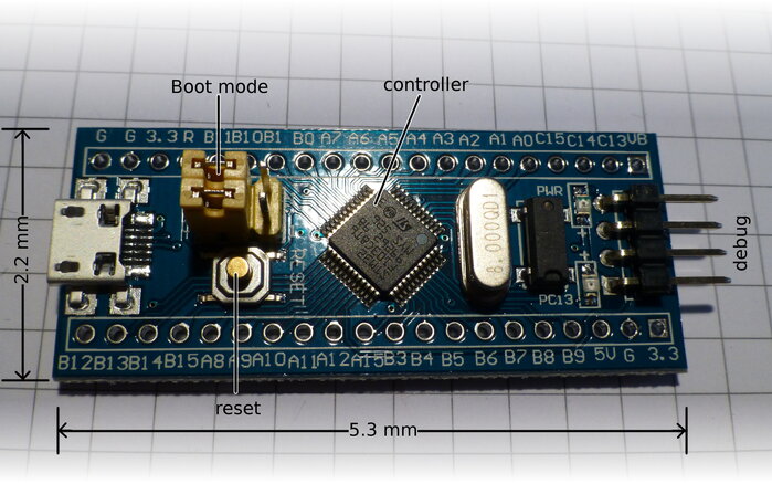
This board is sized 5.3mm × 2.2mm and breadboard compatible. I got mine quite cheap and also undocumented from china. At least i couldn’t find an original from the seller’s site. So i had to do a bit guessing. Luckily most of the boards labeling is just the signal/pin names from the chip. So no need to map from chip pins to a different breakout board numbering scheme.
Board specs:
- Cortex®-M3
- up to: 72Mhz
- ram: 20kb
- flash: 128kb
The jumpers on the board are not labeled. But they are connected to the boot0 and boot1/PB2 (from top to bottom). Both are connected to the stm32 via 100kΩ. The debug header has GND, SWCLK(PA14), SWDIO(PA13) and 3.3V. Reset is also available on as pin R besides the button. The LED is connected from C13 to 3.3V with a 680Ω resistor.
STM32 from scratch, the bare minimum
on 2016-02-20 in stm32-from-scratch
For some future projects i need to bring up a small microcontroller board containing a STM32F103C8T6. But most ARM Cortex-Mx devices are similar for how far this series is going to reach.
Because i like to really know what is running in my microcontroller projects i decided to bring up this device from scratch and document what i needed to do. Where from scratch means i'm allowed to use the basic gnu toolchain (make, g++, ld, as, objcopy), a flash program, the vendor documentation and the register definition headers from STM.
ARM microcontrollers are often said to be complicated and beyond the reach of beginners. I tend to disagree. I started my embedded development with ARM. And i found my trusted gnu toolchain well supported. But i also found big vendor libraries full of cross compiler compatibility and wrappers around simple register manipulation. While these libraries can be a great help if you just want things to be running, they tend to stand in the way of real unterstanding. So here i'm not going to use those libraries.
I made an exception for the hardware register/memory mapped io definitions. Transcibing them from the documentation to C++ code really is just error prone and not very enlightening. For this post i extracted just what is needed from those headers to show how these work. But generelly if the vendor releases them with a truely free license they are nice to use (At least as long as you're no using some C++ meta programming libraries that need definitions in quite a different form. Kvasir comes to mind).
Some of the complexity is also because the ARM ecosystem is a multi vendor ecosystem with actual choice. So much less is hidden in the toolchain, because that is shared among different vendors. Actually having to think about linker scripts is one symptom of this. They do exist for desktop development too, but the toolchain ships with one full of deep knowledge of a well standardized platform. So we tend to ignore them and all the raw power that they contain. Or maybe because the documentation and error handling tends to be a bit rough.
This post details the minimum of c++ code and linker scripts to get the LED on the board to blink. This is actually a bit of code golf. You shouldn't really use code from this post. But it's a good start to have something very minimal to explain and later expand upon.
When starting to bring up a microcontroller the first stop of course is the documentation. In this case consisting of a datasheet(DS5319), a (hardware) reference manual (RM0008), a CPU architecture manual (PM0056) and maybe an errata sheet (learn look at them early to avoid nasty surprises).
Highlights from the datasheet for now are:
- ARM Cortex-M3 CPU, that's what we need to bring up to execute our program.
- Boots with internal 8 MHz RC oscillator selected as clock
- 3.3V with 5V tolerance on many pins, we might need to attach an LED and power to it.
- A block diagram, always handy to have for an quick overview
- The memory map, needed for the linker script
- It has a boot loader mode, so we can get software into the flash without JTAG or similar
As i am using a ready made board with the microcontroller i can ignore most of the pinout for now. Of course i need to find out which pin and thus which
GPIO (general purpose input/output) the LED i want to controll is attached to. The LED is helpfully labeled PC13 which ends up as the port with
index 13 (so zero based counting) of GPIO port C.
All the other details and charateristics are not needed for now. Great 100+ pages i don't need to keep in my head for now.
Ok, now what actually happens when this part is powered on? Well actually, no. In what state is it when is starts to execute code and which code
will it start to execute? The datasheet told me that there is an integrated bootloader, so first i need to know how to enable and disable that.
Section 3.4 "Boot configuration" of the Reference Manual has all i need. There are 2 boot pins (called BOOT0 and BOOT1, but BOOT1 is shared
with a GPIO on the chip i use) that are sampled after reset. For normal boot from embedded flash BOOT0 needs to be pulled to low.
A the datasheet tells me that BOOT0 is pin 35 and a good light and sharp eyes trace that pin to the upper jumper on the board i use (which came completly
without documentation).
With the rom bootloader out of the way i can focus on the environment my early bootup code has to run. ARM Cortex Mx is a very C/C++ friendly architecture so my goal is to boot directly using C++ code. While this is certainly not 100% portable C++ and might even not be actually guaranteed to work with gcc's g++, in pratice this works well.
The boot configuration section also has some information about the initial state of the cpu. But it uses a bit confusing language. So let's refer to the more general documentation. Section 4 of the datasheet contains the memory map in great detail. For now look at the big picture:
- SRAM goes from 0x2000 0000 up
- Flash memory goes from 0x0800 0000 up to 0x0801 FFFF
- Memory from 0x0000 0000 up is aliased depending on the boot pins
ARM memory maps are quite sparse. Bootup state of the cpu is described in the STM Cortex-M3 programming manual. Sections 2.1.1, 2.1.2 and 2.1.3 detail the basic cpu registers and their reset state. The most relevant part is that the initial value of the stack pointer is read from the 32 bit word at 0x00000000 and the initial value of the program counter is read from 0x0000 0004. This is actually the start of the vector table (2.3.4), but for now the other vectors can be ignored. Also it states that the processor starts in privileged(2.3.2) thread mode using the main stack. By the way, the arm stack grows towards lower addresses.
Interrupts are disabled on start. Some arm cores have a memory protection unit (MPU). Section 4.2.6 shows that the reset value of its enable register is off.
So back to the Reference Manual, using BOOT0 pulled low, the addresses starting from 0x0000 0000 are setup to alias 0x0800 0000, that is the main flash area. So that's enough to start writing some code. And some linker configuration. So lets start with the linker script. As i said above the gnu arm toolchain doesn't have special knowledge about specific microcontrollers.
OUTPUT_FORMAT(elf32-littlearm)
OUTPUT_ARCH(arm)
This tells ld that it's going to process arm object files using the elf format as general object file format. The microcontroller of course doesn't use elf, but the elf bits will get stripped off as the very last build step.
MEMORY {
    FLASH : ORIGIN = 0x08000000, LENGTH = 64K
}
The MEMORY command declares memory regions that the linker can use for allocating specific usages. For now we only need one region for the flash part
of the memory map. FLASH is just an identifier to refer to this region later. ORIGIN and LENGTH specify the regions location in the address space.
SECTIONS {
    .vectors : {
        *(.vectors)
    } > FLASH

    .text : {
        *(.text*)
    } > FLASH

}
ELF uses named sections for various parts of code and data. For now the SECTIONS command just instructs ld to put the .vectors section at the
start of the flash filling it with the contents of the .vectors sections of the input files. The second part does similarly with sections whose name
starts with .text, adding them just after the vectors section.
As the flash memory gets aliased to 0x0000 0000 on boot, the vectors section will be readable from 0x0000 0000 and 0x0000 0004 to setup the stack and program counter registers to start the actual program.
On to the C++ code:
void mainFn() {
    // code to follow later
}

extern void (* const vectors[])() __attribute__ ((section(".vectors"))) = {
                (void (*)())0x20000400,
                mainFn,
};
The first part is simple for now. mainFn will be the function where execution starts. But for that to actually happen the vectors table needs
to be setup. That's what the second part does. __attribute__ ((section(".vectors"))) instructs g++ to emit this initialized array into the
section named .vectors to be picked up later by the linker and placed at the very start of the flash section. As C++ is typed and most of the
vector table is later filled with pointers to functions i've choosen to use void (*)() as the basic type of the array. I’ve also made this const
so that matches at c++ level with the final placement of the section in flash. As const implies internal linkage in C++ the extern also is needed
for g++ to actually emit this at C++ level unused data.
Index 0 is the initial value of the stack register. 0x2000 0400 is 1kbyte from the start of the SRAM in the memory map. As stack grows towards lower addresses if the program overflows the stack it will fault, which should be more useful while debugging then just silently corrupting whatever memory happens to come below the stack. 1kbyte should be ok for experimenting, but likely it's much more than needed most programs. Later this will be supplied from the linker. The second value is the address of the function to run on reset, also known as reset handler.
The goal of this simple program is to blink the LED attached for GPIO C13. So on to setting up GPIO port C. Section 9 of the reference manual covers the GPIOs. But this block starts in disabled (i.e. unclocked) state on boot. So Section 7.3 the register part of "reset and clock control" is our first stop. GPIO port C is controlled by the IOP C EN bit in the APB2 EN R register of the RCC. As most peripherial registers are memory mapped in arm this will be a read–modify–write on a memory address.
Mapping all the needed registers oneself doesn't help much in understanding or fine control of the system. So i'll use the vendor provided definition from STM32CubeF1 (i used version 1.2) which are available in BSD (3 clause) licensed form in the directories STM32Cube_FW_F1_V1.2.0/Drivers/CMSIS/Include and STM32Cube_FW_F1_V1.2.0/Drivers/CMSIS/Device/ST/STM32F1xx/Include But for the program in this post i extracted the relevent code to exlpain the general setup of the hardware mapping. The parts needed for enabling the GPIO Port are:
#define     __IO    volatile

typedef struct
{
  __IO uint32_t CR;
  __IO uint32_t CFGR;
  __IO uint32_t CIR;
  __IO uint32_t APB2RSTR;
  __IO uint32_t APB1RSTR;
  __IO uint32_t AHBENR;
  __IO uint32_t APB2ENR;
  __IO uint32_t APB1ENR;
  __IO uint32_t BDCR;
  __IO uint32_t CSR;


} RCC_TypeDef;

#define PERIPH_BASE           ((uint32_t)0x40000000)
#define AHBPERIPH_BASE        (PERIPH_BASE + 0x20000)

#define RCC_BASE              (AHBPERIPH_BASE + 0x1000)

#define RCC                   ((RCC_TypeDef *) RCC_BASE)

#define  RCC_APB2ENR_IOPCEN   ((uint32_t)0x00000010)
So access to memory mapped registers used volatile access to prevent to compiler from any kind of reordering of these accesses. As is usually done
in ARM register definitions all registers of one component are gathered into one struct and a macro is definied that ultimatly ends up as a typecast
of it’s base address to an pointer of this type. Additionally we get a macro that maps bits in the register to values. So the following code in the
mainFn now enables the gpio port component:
RCC->APB2ENR |= RCC_APB2ENR_IOPCEN;
Back to the gpio configuration. Most gpios start up tristated (that is in high impedance mode). This gpio block has 4 bits of configuration for each pin. Thus configuration is split into 2 32-bit registers. The high part of the configuration register contains configuration of output 13. For now i picked any output mode and set it to push-pull mode. Resulting in 0b0011 as configuration. For the rest of the pins floating input mode is selected which is also the reset state. But this way it's a simple set instead of a read–modify–write and the state is more explicitly visible. As the LED's cathod is connected (via a resistor of course) to the GPIO, setting the state of the GPIO to low will activate the LED. One way to set on pin to low is to write to the port bit reset register with the bit corresponding to the pin index set to one. The code (omitting the definition of GPIOC which is similar to how RCC is defined):
    GPIOC->CRH = 0b0100'0100'0011'0100'0100'0100'0100'0100;
    GPIOC->BRR = 1 << 13;
On reset the second line is not strictly needed, because the reset state already has all output data bits of the GPIO as 0. But here i opted to be explicit.
Ok, on to blink the LED. I want 1 Hz and 50% duty cycle. So next we need a 500ms delay. A simple way, when there are no interrupts to add unpredictable additional delay, is just to use a waiting loop. To get the timing right we need to know the exact generated code and how much cycles are taken by each machine instruction. And we need to tell g++ not to optimize away the loop, because a wait loop looks just useless to it.
    int ctr = 1000;
    while (ctr) {
        asm("");
        --ctr;
    }
Apart from the start value for ctr this simple loop is a good delay loop. The asm(""); doesn't emit any code, but g++'s optimizer doesn't considers this asm statement to be removable by optimization, so it’s a easy way to disable code removal. To calculate the right value for ctr we need to look at the generated assembly. I'm using objdump --disassemble here:
  1e:   f44f 737a       mov.w   r3, #1000       ; 0x3e8
  22:   3b01            subs    r3, #1
  24:   d1fd            bne.n   22 <_Z6mainFnv+0x22>
That’s the whole loop, extracted from the 20·ish lines of output from objdump. For most who have read any kind of assembly this looks rather expected. An immediate load of the start value (not part of the loop proper), an substraction of the loop variable and an conditional jump back to the look start. One thing to watch out for when looking at ARM assembly is that the instruction mnemonics used by ARM changed over time(now uses Unified Assembler Language (UAL)), so depending on the tools and documentation it sometimes happens that they mismatch. The subs instruction takes 1 cycle and the bne.n takes 2-4 cycles (e.g. ARM Cortex‑M3 Processor Technical Reference Manual 3.3.1). In simple loops the branch is sufficently easy that in my experience it mostly takes 2 cycles. This all assumes that g++ doesn't start to generated different code. So with the cpu still running on the internal 8MHz clock we get:
        int ctr;
        ctr = (8000000 / 3) / 2;
        // each loop iteration takes 3 cycles to execute.
        while (ctr) {
            asm ("");
            --ctr;
        }
Next step is setting the GPIO to high to disable the LED. The GPIO has a register that allows both setting and resetting individual bits that can be used just like BRR to set the bits: BSRR.
So the final blinking code looks like this:
#include "minsys.h"

void mainFn() {
    RCC->APB2ENR |= RCC_APB2ENR_IOPCEN;
    GPIOC->CRH = 0b0011'0000'0000'0000'0000'0000;
    GPIOC->BRR = 1 << 13;

    while (1) {
        int ctr;
        ctr = (8000000 / 3) / 2;
        // each loop iteration takes 3 cycles to execute.
        while (ctr) {
            asm ("");
            --ctr;
        }
        GPIOC->BRR = 1 << 13;
        ctr = (8000000 / 3) / 2;
        // each loop iteration takes 3 cycles to execute.
        while (ctr) {
            asm ("");
            --ctr;
        }
        GPIOC->BSRR = 1 << 13;
    }
}


extern void (* const vectors[])() __attribute__ ((section(".vectors"))) = {
                (void (*)())0x20000400,
                mainFn,
};
minsys.h here is the minimal definitions extracted from the mbed board headers.
The last step is to actually compile this and upload it to the board to test:
arm-none-eabi-g++ -c -mcpu=cortex-m3 -mthumb --std=c++14 -O2 -fno-rtti -fno-exceptions main.cpp -o main.o
Here -mcpu=cortex-m3 -mthumb tells g++ what cpu the code should be generated for. While -mthumb looks redundant for an cpu that only supports thumb code, g++ requires it nevertheless. I use c++14 mode because it’s constexpr support comes in handy even with embedded development. -fno-rtti and -fno-exceptions disable runtime type information and the complete exception infrastructure in the generated code. This is important because both need runtime support code and that infrastructure is rather large and thus hard (or impossible) to fit into small microcontrollers.
arm-none-eabi-g++ -mcpu=cortex-m3 -mthumb -Tlinkerscript.ld -nostartfiles main.o -o main.elf
Next step is to link the code. -Tlinkerscript.ld specifies the linker script that should be used for linking, replacing ld’s default linker script. In this case i saved linker script in the file linkerscript.ld. -nostartfiles disables the usage of any toolchain provided object files for the entrypoint and start.
The linker generates a fully linked output that still contains elf metainformation like section names and various other bookkeeping data.
arm-none-eabi-objcopy -O binary main.elf main.bin
This metadata is stripped away by objcopy when copying to a binary (or ihex) format. objcopy in this mode produces a file that starts with the data of the loaded section with the lowest load address and pads space between sections with zero bytes. In this example there are no gaps between the sections.
A hexdump of the result still fits nicely in a few lines:
000000 00 04 00 20 09 00 00 08 0b 4b 70 b4 4f f4 00 54
000010 19 46 22 46 09 4d 4f f4 40 16 a8 69 40 f0 10 00
000020 a8 61 5e 60 5c 61 06 4b 01 3b fd d1 04 4b 4a 61
000030 01 3b fd d1 0a 61 f6 e7 00 10 01 40 00 10 02 40
000040 55 58 14 00
Well not that we are going to analyse this. But we see that this generated 68 bytes of binary.
The binary can now be uploaded to flash. I use stm32flash which is just an apt install stm32flash away with debian. For this we need to set the board to bootloader mode, so pull boot0 up to 3.3V and push reset. Then stm32flash should be able to detect the controller using an 3.3V or 5V logic level serial interface.
$ stm32flash /dev/ttyUSB1
stm32flash 0.4

http://stm32flash.googlecode.com/

Interface serial_posix: 57600 8E1
Version      : 0x22
Option 1     : 0x00
Option 2     : 0x00
Device ID    : 0x0410 (Medium-density)
- RAM        : 20KiB  (512b reserved by bootloader)
- Flash      : 128KiB (sector size: 4x1024)
- Option RAM : 16b
- System RAM : 2KiB
To flash and run use:
stm32flash -w main.bin /dev/ttyUSB1
stm32flash -g0 /dev/ttyUSB1
Now the board should blink it’s LED.
For full code see here